


28
C
ONFIGURING
F
RAME
R
ELAY
AND
M
ULTILINK
F
RAME
R
ELAY
28.1 Layer Two Configurations
FR and MFR
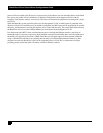
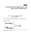
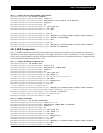
Figure 45 outlines a Multilink Frame Relay (MFR) configuration with three sites. PVC 16 connects Site 1 to Site 3,
while PVC 31 connects Site 2 to Site 3. The Frame Relay switching equipment is represented simply as a Frame cloud.
Figure 45 MFT Configuration
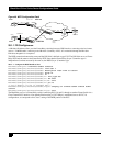
Figure 46 provides greater detail, including the use of a LR1104A inside the cloud as a Frame Relay switching device,
and LR1114A series units at the CPE sites 1 and 2.
Frame
Cloud
Tasman 1450
Tasman 1400
Router
SITE
3
S
ITE 2
S
ITE 1
Router
Router
PVC 16
100 Base-T
HSSI
PVC 16
PVC 16
PVC 31
2 x T1
PVC 31
4 x T1
LR1114A
LR1114A