


Applications
33
Basic Frame Relay Configuration
North American routers with at least one non-ISDN interface are configured to have frame
relay enabled for that interface by default. Routers shipped outside of North America with
at least one non-ISDN interface will have frame relay disabled on that interface as a default
setting. See the following page for instructions on switching Frame relay from disabled to
enabled.
If the router is configured as a frame relay router, it will communicate over WAN
connections to other Frame Relay units via Frame Relay Permanent Virtual Circuits (PVC).
From 1 to 128 PVC’s may be defined to connect to other frame relay units. Before the
router can establish a PVC connection to another frame relay router, at least one PVC must
be defined. The router is pre-configured to query the frame relay service to auto-learn the
required parameters; they may also be set manually.
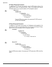
The DLCI (Data Link Connection Identifier) number for the PVC is assigned by the frame
relay service provider. The PVC must be defined on at least one physical links on the
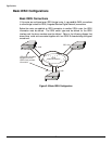
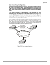
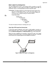
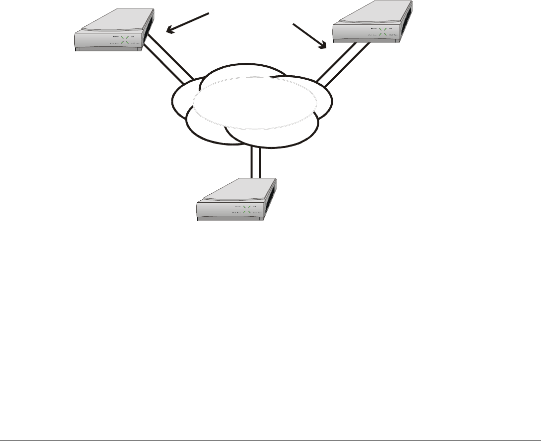
router. Refer to the following diagram that shows three router units connected together
with two PVCs being configured on each unit. The configuration of the PVCs within the
frame relay cloud is controlled by the frame relay service provider.
Figure 2 -8 Frame Relay configuration
Frame Relay PVC
WAN connections
DLCI numbers
assigned for these
PVCs from the
frame relay provider.
50
51
52
53
54 55