


Interface Pinouts
81
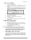
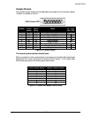
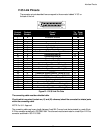
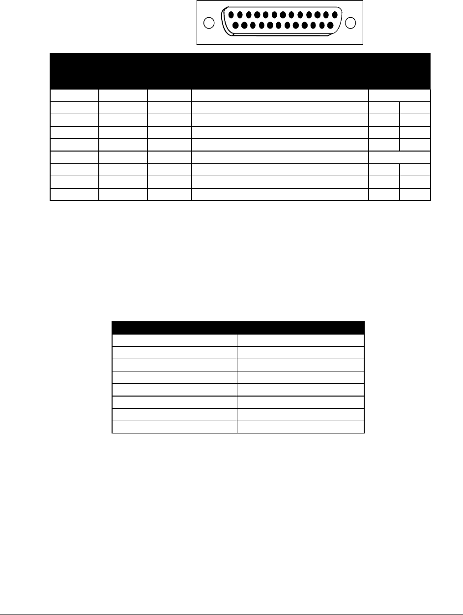
Console Pinouts
The connector shown here and pinouts described here correspond to the connector labeled
“Console” on the back of the unit.
DB25 Female DCE
13
1
25
14
Contact
Number
CCITT
Circuit
Number
IEEE
Circuit
Desig.
Circuit
Name
Direction
To From
DCE DCE
1 101 AA Protective Ground NA
2 103 BA Transmitted Data X
3 104 BB Received Data X
5 106 CB Clear to Send X
6 107 CC Data Set Ready X
7 102 AB Signal Ground NA
8 109 CF Received Line Signal Detector (CD) X
20 108.2 CD Data Terminal Ready X
22 125 CE Ring Indicator X
Figure D-3 Console Pinouts
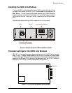
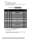
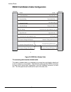
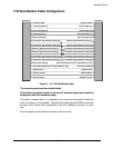
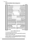
The connecting cable must be a shielded cable.
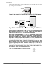
When connecting the router console directly to a modem, a null modem cable must be used
because both the router console and the modem are DCE devices. A null modem cable
with pinouts according to the following figure must be used.
router Contact Number Modem Contact Number
8 20
3 2
2 3
20 8
7 7
4 5
5 4
22 22
Figure D-4 Console Null Modem Cable Pinouts