


Interface Pinouts
84
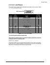
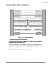
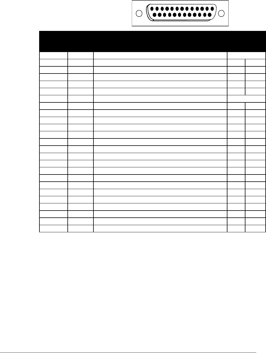
RS442 & RS530 Link Pinouts
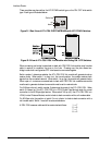
The connector shown here and pinouts described here correspond to the connector labeled
“RS530” on the back of the unit.
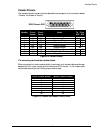
DB25 Female DTE
13
1
25
14
Contact
Number Circuit
Circuit
Name
Direction
To From
DCE DCE
1 Shield Protective Ground NA
2 BA (A) Transmitted Data X
3 BB (A) Received Data X
4 CA (A) Request to Send X
5 CB (A) Clear to Send X
6 CC (A) Data Set Ready X
7 AB Signal Ground NA
8 CF (A) Received Line Signal Detector X
9 DD (B) Receive Signal Element Timing (DCE Source) X
10 CF (B) Received Line Signal Detector X
11 DA (B) Transmit Signal Element Timing (DTE Source) X
12 DB (B) Transmit Signal Element Timing (DCE Source) X
13 CB (B) Clear to Send X
14 BA (B) Transmitted Data X
15 DB (A) Transmit Signal Element Timing (DCE Source) X
16 BB (B) Received Data X
17 DD (A) Receive Signal Element Timing (DCE Source) X
18 LL Local Loopback X
19 CA (B) Request to Send X
20 CD (A) Data Terminal Ready X
21 RL Remote Loopback X
22 CC (B) Data Set Ready X
23 CD (B) Data Terminal Ready X
24 DA (A) Transmit Signal Element Timing (DTE Source) X
25 ----------
Figure D-7 RS530 Link Pinouts
The connecting cable must be a shielded cable.
Circuits which are paired (contain an (A) and (B) reference) should be connected to
twisted pairs within the connecting cable.