


724-746-5500 | blackbox.com
724-746-5500 | blackbox.com
Page 13
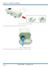
Chapter 3: Hardware Installation
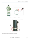
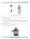
Figure 3-3. Replacing the cover.
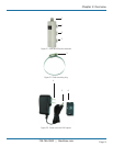
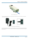
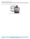
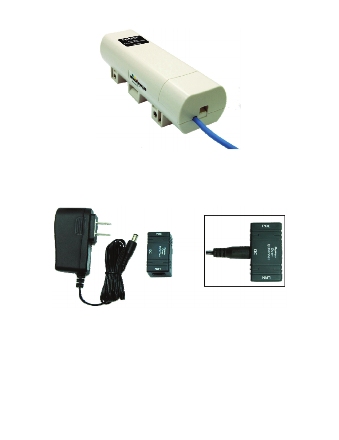
4. Take out the power cord and PoE injector, and plug the power cord into the DC port of the PoE injector as the right-side
picture in Figure 3-4 shows.
Figure 3-4. Installing the power cord and PoE injector.
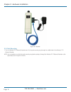
5. Put what you assembled in step 3 and step 4 together by plugging the other side of the Ethernet cable from step 3 into the
PoE port of the PoE injector shown in step 4. When you finish step 5, the extender, power cord, and PoE injector will appear as
shown in Figure 3-5.