


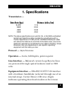

9
SHM-B ASYNC
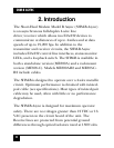
3. Installation
Installation involves three basic steps: four-wire
connections; EIA-232 connection; switch settings.
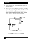
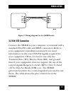
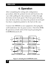
3.1 Four-Wire Connections
Figure 1 shows the location of the terminal block on the
circuit board. Refer to Figure 2 to make the proper
connections between two SHM-B units.
NOTE: Transmit + (TX+) on one modem is wired
to Receive + (RX+) on the other modem; Transmit -
(TX-) is wired to Receive - (RX-). A ground
connection is optional.
1. If the unit is assembled, separate the top and
bottom panels at the front of the unit.
2. Push the rear connector to force out the front
panel and printed circuit board.
3. Route the four-wire cable through the open hole in
the rear panel of the enclosure.
4. Strip each of the four wires about
1
⁄8".