


11
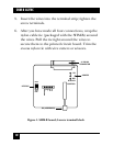
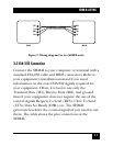
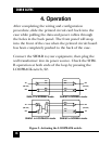
SHM-B ASYNC
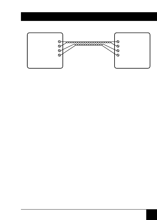
Figure 2. Wiring diagram for two SHM-B units.
3.2 EIA-232 Connection
Connect the SHM-B to your computer or terminal with a
standard EIA-232 cable and DB25 connectors. Refer to
your equipment’s installation manual if you need
information on the exact EIA-232 signals required for
your equipment. Often, it is best to use only the
Transmit Data (TD), Receive Data (RD), and ground
lines if your equipment does not require the use of the
control signals Request To Send (RTS), Clear To Send
(CTS), Data Set Ready (DSR), etc. The SHM-B
generates levels for the control signals if you need to use
them. The table shows the pin connections at the
SHM-B.
TX+
TX-
RX+
RX-
RX+
RX-
TX+
TX-
SHM #1 SHM #2