724-746-5500 | blackbox.com
724-746-5500 | blackbox.com
Page 13
Chapter 3: Installation and Initial Setup
If you select RS-232 mode when you configure the Modbus Hardened Serial Server, you must connect the Modbus serial network
to the Modbus Hardened Serial Server via a serial cable. The LES431A is a DTE. If the Modbus network is a DTE, use a null-
modem (crossover) cable. If the Modbus network is a DCE, use a straight-through cable. DTE and DCE ports are complementary;
the output signals on a DTE port are inputs to a DCE port, and output signals on a DCE port are inputs to a DTE port. The signal
names match each other and connect pin-for-pin. Signal flow is in the direction of the arrows (see Table 3-1, below).
Table 3-1. DTE to DCE Connections.
DTE Device (Computer) DB9 DCE Device (Modem) DB9
Pin # RS-232 Signal Names Signal Direction Pin # RS-232 Signal Names
1 Carrier Detect (CDA) <---------------------------- 1 Carrier Detect (CD)
2 Receive Data (RX) <---------------------------- 2 Receive Data (RX)
3 Transmit Data (TX) ----------------------------> 3 Transmit Data (TX)
4 Data Terminal Ready (DTR) ----------------------------> 4 Data Terminal Ready (DTR)
5 Signal Ground (SG) ----------------------------- 5 Signal Ground (SG)
6 Data Set Ready (DSR) <---------------------------- 6 Data Set Ready (DSR)
7 Request to Send (RTS) ----------------------------> 7 Request to Send (RTS)
8 Clear to Send (CTS) <---------------------------- 8 Clear to Send (CTS)
9 Ring Indicator (RI) <---------------------------- 9 Ring Indicator (RI)
Soldered to DB9 metal—Shield (FGND) ----------------------------- Soldered to DB9 metal—Shield (FGND)
If you select RS-422 mode, RS-485 2-wire mode, or RS-485 4-wire mode when you configure the Modbus Hardened Serial
Server, you must connect the Modbus network appropriately, via the 5-position terminal block.
NOTE: Refer to Appendix B for connector pinout information.
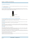
Diagram Format
Rule Size: 0.013
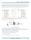
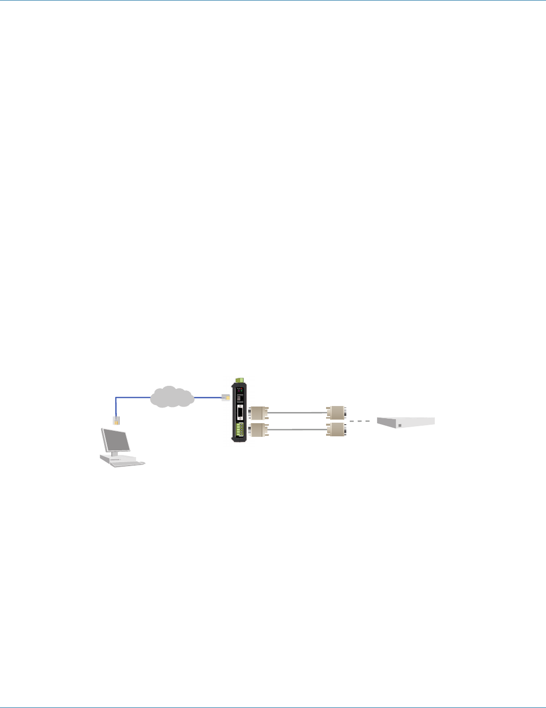
PC
Serial device
RS-232 serial cable
Network
RS-422/485 cable
Modbus
Hardened Serial
Server (LES431A)
Figure 3-2. LES431A connections.
3.3 Connecting Modbus Hardened Serial Servers to a Network
When connecting a Modbus Hardened Serial Server equipped with a 10BASE-T/100BASE-TX network connection (RJ-45
connector) to an Ethernet network drop, use a standard unshielded twisted-pair cable. PCs configuring and/or communicating
with the Modbus Hardened Serial Server are also connected to the network.
3.4 Modbus Hardened Serial Server Configuration Connections
The Modbus Hardened Serial Servers can be configured using three methods:
• Via the network using Modbus Hardened Serial Server Software.
• Via the network using a Web browser.
• Via a serial port using Modbus Hardened Serial Server Software (Console Mode).


