


43
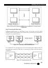
2.048Mb
p
s Wireless Modem
TECHNICAL: 0118 931 2233
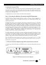
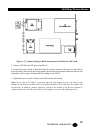
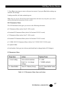
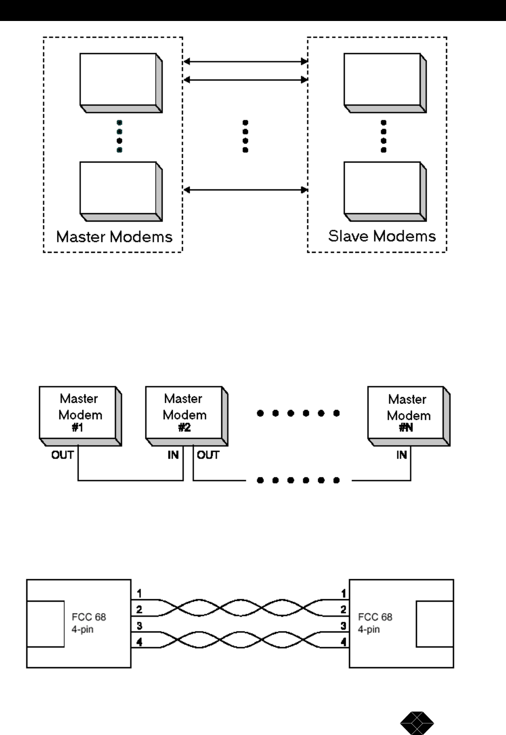
Figure 2-20. Several Co-located 2.048Mbps Wireless Modems in a “center-to-center”
configuration.
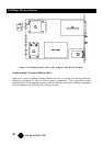
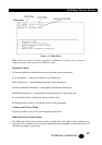
Step-3 Connecting the Master units
Establishing synchronization is a “Hot Plug-In” process: You can add a new link without
interfering with the normal operation of the working link(s), provided the relevant parameters
are properly set (as described above).
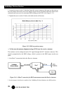
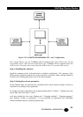
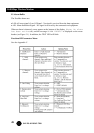
Figure 2-21. Connecting Units for Synchronization
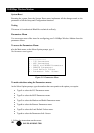
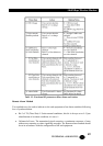
Use a standard FCC 68 4-pin plug (male) to FCC 68 4-pin plug (male) telephone cable with
two twisted pairs (supplied by Black Box) to interconnect the Master units that should be
synchronized.
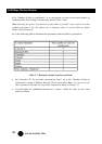
Figure 2-22. Synchronization Cable