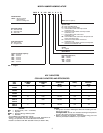
SELECTION PROCEDURE (WITH EXAMPLE)
I DETERMINE COOLING AND HEATING REQUIRE-
MENTS AT DESIGN CONDITIONS:
Given:
Required Cooling Capacity (TC) ..........35,000 Btuh
Sensible Heat Capacity (SHC) ...........25,000 Btuh
Required Heating Capacity ..............60,000 Btuh
Condenser Entering Air Temperature ............95F
Indoor-Air Temperature ...........80Fedb, 67 F ewb
Evaporator Air Quantity...................1200 Cfm
External Static Pressure ..................0.1in.wg
Electrical Characteristics ..................208-1-60
II SELECT UNIT BASED ON REQUIRED COOLING
CAPACITY.
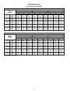
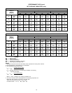
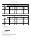
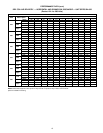
Enter Net Cooling Capacities table at condenser entering
temperature of 95 F. Unit 583A--036 at 1200 cfm and 67 F
ewb (entering wet bulb) will provide a total capacity of
35,000 Btuh and a SHC of 25,200 Btuh. Calculate SHC
correction, if required, using Note 4 under Cooling Capaci-
ties tables.
III SELECT HEATING CAPACITY OF UNIT TO PROVIDE
DESIGN CONDITION REQUIREMENTS.
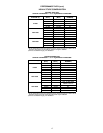
In the Heating Capacities and Efficiencies table on
page 4, note that the unit 583A--036090 will provide
71,910 Btuh with an input of 88,000 Btuh.
IV DETERMINE FAN SPEED AND POWER REQUIRE-
MENTS AT DESIGN CONDITIONS.
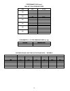
Before entering the air delivery tables, calculate the total
static pressure required. From the
given
example, the Wet
Coil Pressure Drop Table, and the Filter Pressure Drop
table on page 16, find at 1200 cfm:
External static pressure 0.1 in. wg
Wet Coil 0.1 in. wg
Filter 0.2 in. wg
Total static pressure 0.4 in. wg
Enter the table for Dry Coil Air Delivery — Horizontal and
Downflow Discharge on page 15. For 208 v operation, de-
duct 10% from value given. At 0.4 ESP (external static
pressure), the fan will deliver 1213 cfm at medium speed.
The fan speed should be set at medium speed.
V SELECT UNIT THAT CORRESPONDS TO POWER
SOURCE AVAILABLE.
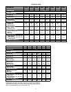
The Electrical Data table on page 20 shows that the unit is
designed to operate at 208-1-60.
11


