IPX R
OUTING
N
ETWORK
OVERVIEW
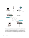
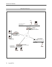
This sample network uses IPX protocol to allow remote devices and their servers to communicate.
It illustrates a master network in which the central-site CyberSWITCH communicates with:
• Remote bridges using a Remote LAN interface, and
• A remote IPX router using a traditional WAN interface.
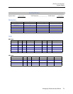
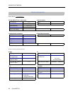
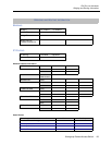
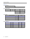
To better understand the layout of this network, refer to the following Network Topology
Worksheet. Note that the central-site master network is in Detroit. Tampa and Orlando represent
the bridged sites, and Dallas represents the remote WAN site.
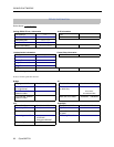
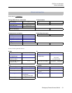
System details appear in the worksheets and are followed by the unique portion of this network’s
configuration procedure.
BUSINESS ASSUMPTIONS
• All devices are PPP-compliant.
• Central site is on a PBX; therefore, 9 required to dial out.
• No File Servers at Tampa or Orlando sites.
• Uses the On-node Device Database for authentication database.
• Uses PAP to authenticate remotes; CHAP on central site.
• Assumes Dallas Network supports Triggered RIP/SAP (i.e., compatible with central site).
• Central site dials out only to Dallas; Tampa and Orlando dial in to central site.
• Central site supports two BRI lines (4-port BRI card), with 5ESS custom switch configuration.
• Assumes bridging enabled at system level (at central site) so that the device routes enabled
network-layer protocols and bridges all other packets.
• Uses no filtering; unrestricted mode.
INITIAL INSTALLATION STEPS
The initial steps in the CyberSWITCH installation process are basically the same no matter how
detailed the network. These steps are:
• completing the requirement worksheets
•ordering ISDN service
• powering on the system
• accessing Release Notes
• connecting an administration console
• setting up Telnet access
• upgrading system software
• changing defaults to secure system
• returning configuration to factory defaults
The chapters Accessing the CyberSWITCH and Upgrading System Software (in the User’s Guide)
describe each of these steps in detail.


