


FE Switch Module User Guide Page 2-1
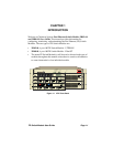
CHAPTER 2
CONNECTING TO THE NETWORK
This chapter provides reference material and instructions that network
administrators can use to configure the Fast Ethernet Switch Modules.
For instructions on adding a switch module to the ATX, see Chapter 5,
Adding/Swapping Modules
.
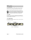
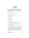
2.1 POWER-UP LED SEQUENCE
Watch the LED sequence during power-up. It takes about 1 minute for the
ATX to complete the power-up diagnostics. The ATX begins system
diagnostics on the PPE (topmost module) and then individually on each
installed module, starting at the top and working down to the bottom.
Using both processors, the specific power-up tests run on the switch
module are:
• ROM checksum test
• Instruction memory test
• Memory map tests
• Interrupt tests
• Fast Ethernet data loopback tests
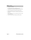
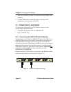
The power-up LED sequence for the Fast Ethernet module is as follows:
1. All LEDs flash.
2. The PWR LED remains on, and the TX LEDs flash.
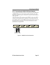
3. On each switch module, the following occurs:
a. The PROC LED comes on for 5 seconds, blinks, then remains lit.
b. The RX and TX LEDs flash momentarily.