


Connecting to the Network
6E122-26, 6E132-25, 6E123-26 and 6E133-25 User’s Guide 3-11
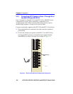
Connect an FE-100TX to a twisted pair segment as follows:
1. Ensure that the device connected to the other end of the segment is
powered ON.
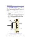
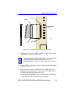
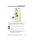
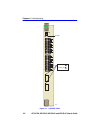
2. Connect the twisted pair segment to the module by inserting the RJ45
connector on the twisted pair segment into the RJ45 port on the
module shown in Figure 3-6.
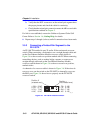
3. Verify that a link exists by checking that the port RX LED is on
(flashing amber, blinking green, or solid green). If the RX LED is off,
perform the following steps until it is on:
a. Verify that the 100BASE-TX device at the other end of the twisted
pair segment is powered up.
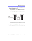
b. Verify that the RJ45 connector on the twisted pair segment has the
proper pinouts.
c. Check the cable for continuity.
d. Make sure that the twisted pair connection meets dB loss and cable
specifications outlined in Section 2.3.
e. Confirm that the crossover switch is in the correct position.
If a link is not established, contact the Cabletron Systems Global Call
Center. Refer to Section 1.6, Getting Help, for details.