


Chapter 3: Installation
3-12 6E122-26, 6E132-25, 6E123-26 and 6E133-25 User’s Guide
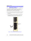
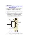
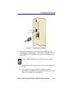
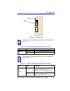
3.5.4 Connecting a Fiber Optic Segment to the
FE-100FX and FE-100F3
The FE-100FX and FE-100F3 have an SC style network port (see
Figure 3-7). Cabletron Systems supplies fiber optic cable that uses SC
style connectors that are keyed to ensure proper crossing over of the
transmit and receive fibers.
Fiber Optic Network Connection
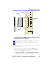
1. Remove the protective plastic covers from the fiber optic ports on the
applicable port on the module and from the ends of the connectors.
2. Insert one end of the SC connector into the FE-100FX or FE-100F3
installed in the 6E12X-26. See Figure 3-7.
3. At the other end of the fiber optic cable, attach the SC connector to the
other device.
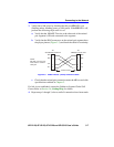
!
CAUTION
An odd number of crossovers (preferably one) must be
maintained between devices so that the transmit port of one
device is connected to the receive port of the other device and
vice versa.
If the fiber optic cable being used has SC style connectors that
do not resemble MIC style connectors, or has SC connectors
on one end and a different type on the other, such as ST
connectors, ensure that the proper crossing over occurs.
!
CAUTION
The FE-100F3 uses Class 1 lasers. Do not use optical
instruments to view the laser output. The use of optical
instruments to view laser output increases eye hazard. When
viewing the output optical port, power must be removed from
the network adapter.
!
CAUTION
Do not touch the ends of the fiber optic strands, and do not let
the ends come in contact with dust, dirt, or other contaminants.
Contamination of the ends causes problems in data
transmissions. If the ends become contaminated, clean them
with alcohol using a soft, clean, lint-free cloth.