


Troubleshooting 4-1
4
Troubleshooting
This chapter provides information concerning the following:
• Using the LANVIEW diagnostic and status monitoring system (Section 4.1)
• Troubleshooting network and module operational problems (Section 4.2)
• Using the RESET button (Section 4.3)
4.1 USING LANVIEW
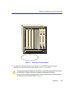
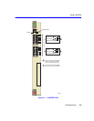
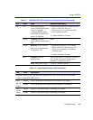
The SmartSwitch modules use Cabletron Systems’ built-in visual diagnostic and status monitoring
system called LANVIEW. The LANVIEW LEDs (Figure 4-1) allow quick observation of the
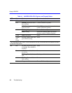
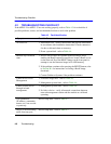
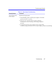
network status to aid in diagnosing network problems. Refer to Table 4-1 for a description of the
LEDs.
Refer to the HSIM or VHSIM User’s Guide for a description of the HSIM or VHSIM LEDs.
4.1.1 The LED Mode Switch
The SmartSwitches have an LED mode switch, located on the front panel, that allows the user to
change the function of the LEDs. Refer to Figure 4-1 for the location of the LED mode switch.
When the switch is in the UP position, the LEDs indicate the receive (RX) and transmit (TX) status
of the fixed ports. When the mode switch is in the DOWN position, the LEDs indicate at what
speed the applicable port is currently operating (10 Mbps or 100 Mbps) and if the applicable port
is operating in standard or full duplex mode.
NOTE
The terms flashing, blinking, and solid used in the LED definition tables of this chapter
indicate the following:
Flashing indicates an irregular LED pulse.
Blinking indicates a steady LED pulse, (approximately 50% on, 50% off).
Solid indicates a steady LED light. No pulsing.