1-3
Introduction
or full duplex mode. Operating in standard Ethernet mode limits bandwidth to 10
Mbps per port, while operating in duplex mode doubles bandwidth from 10
Mbps to 20 Mbps per port.
Management Information Base (MIB) Support
The 9E428-12/36 and 9E429-12/36 modules provide MIB support including:
• RMON (RFC-1271)
• IETF MIB II (RFC-1213)
• IETF Bridge MIB (RFC-1493)
and a host of other Cabletron Enterprise MIBs.
INB
The 9E428-12/36 and 9E429-12/36 modules attach to INB-B of the SmartSwitch
9000 Backplane. The INB Backplane is designed to transport fixed length data
blocks between modules in the SmartSwitch 9000 using an INB Time Division
Multiplexing (ITDM) design. The SmartSwitch 9000 INB bus delivers 2.0 Gbps of
true data bandwidth with all control and management communication being
serviced on the 8 bit out-of-band bus. The time slices of the INB manager operates
in all three modes at once, without user intervention.
Arbitration for the backplane is accomplished in the INB Time Division
Multiplexing (ITDM) logic. The arbitration is a three-level scheme that ensures
that no one can get the backplane for more than one time slice at a time.
The ITDM RAM contains 256 4-bit locations. This RAM is used to hold slot
numbers of modules participating in INB backplane arbitration. The arbitration
engine accesses this RAM once every time slice to get a slot number. That slot
number will be granted access on the next time slice if it is requesting. The
arbitration engine is always one time slice ahead, meaning that the value read
from the RAM is for the next time slice, not the current time slice.
LANVIEW LEDs
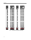
The 9E428-12/36 and 9E429-12/36 modules use LANVIEW – the Cabletron
Systems built-in visual diagnostic and status monitoring system. With LANVIEW
LEDs, you can quickly identify, at a glance, system status, as well as the device,
port, and physical layer status. Two LEDs indicate the transmission and reception
of data from the INB SmartSwitch 9000 backplane connection. Each of the 12
Ethernet front panel ports features two LEDs per port to indicate the port’s
Administrative status (enabled/disabled), LINK status (Link/Nolink), and Data
Activity (receiving and transmitting data).
For a complete list of supported MIBs, refer to the release notes provided in the
9E428-12/36 and 9E429-12/36 modules package.
NOTE


