


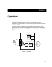


Operation
3-2
System Management Buses
There are two management channels within the SmartSwitch 9000 system: the
SMB-1 and the SMB-10. These buses provide out-of-band management and inter-
module management communication.
SMB-1 Bus
The SMB-1 is a 1Mbs management bus located within the SmartSwitch 9000. This
bus is utilized by all diagnostic controllers in the system, including connectivity
modules, power supply modules and the environmental module. The SMB-1
transports inter-chassis information between system components, such as power
and environmental information, as well as diagnostic messages. Periodic
loop-back tests are performed by all modules that share this bus to ensure the
validity of SMB-1. In the event a failure is detected on SMB-1, the SMB-10 may be
used as an alternate communication channel.
SMB-10 Bus
The SMB-10 is a 10Mbs management bus located within the SmartSwitch 9000
that is also used for inter-chassis communication of modules, as well as serving as
an out-of-band management channel into the SmartSwitch 9000. The SMB-10 is
externalized from the chassis via an optional Ethernet Port Interface Module
(EPIM) located on the front of the Environmental Module. Through an EPIM
connection, full SNMP management of the SmartSwitch 9000 is available out-of-
band from user data. Modules which share the SMB-10 bus periodically send out
loop-back packets to ensure the validity of SMB-10. In the event a fault is detected
on the SMB-10, the SMB-1 can be used as an alternate communication channel by
the modules.
System Diagnostic Controller
This diagnostic controller is composed of a Z-80 microprocessor and the
supporting logic. The diagnostic controller is designed to control the power-up
sequencing of modules, monitor the 9E106-06 input and output power
parameters, keep watch over the main Host Processor, as well as monitor the
temperature and control the SMB LANVIEW diagnostic LED. Although the
diagnostic controller and the main Host Processor can operate independently of
each other if needed, they exchange information about each others status and
overall module condition. The information gathered by the diagnostic controller
is available to the network manager via local/remote management and the LCD
located on the Environmental Module. The 9E106-06 has been designed so that in
the event of a diagnostic controller fault, the 9E106-06 continues to function.