


EPIMs
A-6
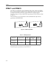
Figure A-5. The EPIM-A and EPIM-X
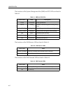
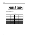
Table A-4 lists the DB-15 pinouts.
Table A-4. DB-15 Pinouts
Pin Number Represents Pin Number Represents
1 Logic Ref. 10 Transmit -
2 Collision + 11 Logic Ref.
3 Transmit 12 Receive -
4 Logic Ref. 13 Power (+12Vdc)
5 Receive 14 Logic Ref.
6 Power Return 15 No Connection
7 No Connection Connector Shell Positive Ground
9 Collision -