


Installing the SmartSwitch 9000 Module
2-2
2. Attach the antistatic wrist strap (refer to the instructions outlined on the
antistatic wrist strap package).
3. Unlock the top and bottom plastic locking tabs of the module faceplate.
4. Slide out the module, and place it on its side with the internal components
facing up.
5. Remove and save the two faceplate mounting screws securing the
HSIM/VHSIM coverplate and remove the coverplate.
6. Remove and save the two standoff screws.
7. Place the HSIM/VHSIM behind the module faceplate.
8. Insert the connectors of the HSIM/VHSIM into the host device connector pins
on the module.
9. Press down firmly on the back of the HSIM/VHSIM until the pins slide all the
way into the connector holes.
10. Secure the HSIM/VHSIM to the faceplate using the two screws saved in
step 5.
11. Secure the HSIM/VHSIM to the standoffs with the two screws saved in step 6.
12. Reinstall the interface module in the chassis.
13. Reattach the network cabling to the interface module.
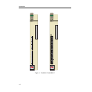
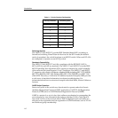
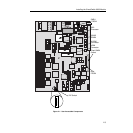
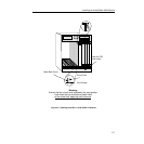
User Accessible Components
Figure 2-1 shows the various components that are accessible to the user. These
consist of an eight-position DIP switch, replaceable PROMs and sockets for RAM.
These components will be used for future upgrades. Instructions for installing the
components will be supplied with the upgrade kit.
Ensure that the HSIM/VHSIM connectors align with the host device connector
pins to prevent bending the pins. This can damage both the HSIM/VHSIM and
the module.
!
CAUTION
In step 11 ensure that the standoffs on the interface module align with the standoff
screw holes on the HSIM/VHSIM to prevent bending pins.
!
CAUTION