


2-5
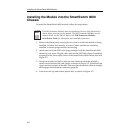
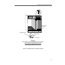
Installing the SmartSwitch 9000 Module
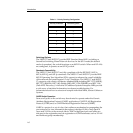
Using DIP Switch 6
The purpose of DIP switch 6 is to force a Flash download from a BootP server
through the EM-EPIM. The first step in this process is to configure the BootP
server. Configurations of BootP servers can differ from platform to platform and
from one operating system to another. Read the user’s manual on BootP and
TFTP serving for the correct files to edit and the correct files to execute for the
server. After configuration of the BootP server the module can then have the
switch state changed on dip switch 6 to initiate BootP and TFTP requests.
When the state of dip switch 6 is changed, the module begins requesting a BootP
server in an attempt to receive a Flash image download. The modules boot PROM
initiates a BootP sequence. During this sequence, the module requests an IP
address and a filename from the BootP server. The module then requests a TFTP
of the file and receives the download of the image. The module will not function
until the Flash image is downloaded from the BootP and TFTP server.
If a BootP and TFTP are not intended at this time, this process may be stopped by
resetting the module. Resetting is done by pushing the reset button on the
module, power cycling the chassis, or removing the module from the chassis and
re-inserting. (See section titled
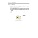
The Reset Switch
on page 2-8.) After resetting, the
module again looks for a BootP server, but will time-out after about four minutes.
After the time-out, the module boots from Flash memory. The next time the
power is cycled, the module will boot from Flash memory and not request the
BootP server.
1. Caution: Do not toggle Switch 8 unless you intend to reset the user-
configured passwords to their factory default settings.
2. Caution: Do not toggle Switch 7 unless you intend to reset the user
parameters to the factory default settings.
!
CAUTION