


Installing the SmartSwitch 9000 Module
2-4
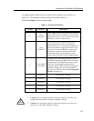
Using DIP Switch 6
The purpose of DIP switch 6 is to force a Flash download from a BootP server
through the EM-EPIM. The Þrst step in this process is to conÞgure the BootP
server. ConÞgurations of BootP servers can differ from platform to platform and
from one operating system to another. Read the userÕs manual on BootP and TFTP
serving for the correct Þles to edit and the correct Þles to execute for the server.
After conÞguration of the BootP server the module can then have the switch state
changed on dip switch 6 to initiate BootP and TFTP requests.
When the state of dip switch 6 is changed, the module begins requesting a BootP
server in an attempt to receive a Flash image download. The modules boot PROM
initiates a BootP sequence. During this sequence, the module requests an IP
address and a Þlename from the BootP server. The module then requests a TFTP
of the Þle and receives the download of the image. The module will not function
until the Flash image is downloaded from the BootP and TFTP server.
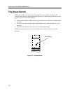
If a BootP and TFTP are not intended at this time, this process may be stopped by
resetting the module. Resetting is done by pushing the reset button on the
module, power cycling the chassis, or removing the module from the chassis and
re-inserting. (See the section titled
The Reset Switch on page 2-6.) After resetting,
the module again looks for a BootP server, but will time-out after about four
minutes. After the time-out, the module boots from Flash memory. The next time
the power is cycled, the module will boot from Flash memory and not request the
BootP server.
Installing the Module into the SmartSwitch 9000
Chassis
To install the SmartSwitch 9000 module, follow the steps below:
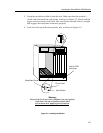
1. Remove the blank panel covering the two slots in which the module is being
installed. All other slots must be covered, if other modules are not being
installed, to ensure proper airßow and cooling.
2. Attach one end of the ESD wrist strap packaged with the SmartSwitch 9000
chassis to your wrist. Plug the other end into the ESD Wrist Strap Grounding
receptacle in the lower right corner of the SmartSwitch 9000 chassis shown in
Figure 2-2.
The INB Terminator Modules must be installed on the rear of the fourteen slot
chassis before powering up this module. The INB Terminator Modules are not
required on the six slot chassis. Refer to the INB Terminator Modules
Installation Guide for information and installation procedure.
NOTE