


4-1
Chapter 4
LANVIEW LEDs
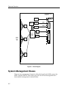
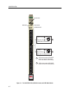
The front panel LANVIEW LEDs indicate the status of the module and may be
used as an aid in troubleshooting. Figure 4-1 shows the LANVIEW LEDs of the
9H532-24, 9H533-24, 9H531-24 and 9H539-24 module.
The LED Mode Switch
The 9H532-24 and 9H533-24 have an LED mode switch, located on the front
panel, that allows the user to change the function of the switch port LEDs. Refer to
Figure 4-1. When the switch is in the UP position, the LEDs indicate the receive
(RX) and transmit (TX) status of the Þxed ports. When the mode switch is in the
DOWN position, the LEDs indicate at what speed the applicable port is currently
operating (10 Mbps or 100 Mbps) and if the applicable port is operating in
standard (half) or full duplex mode.
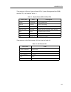
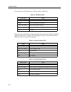
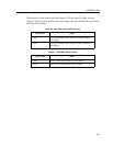
Table 4-4 and Table 4-5 provide the deÞnitions of the LED states that occur when
the LED mode switch is in the UP position. Table 4-6 and Table 4-7 provide the
deÞnitions of the LED states that occur when the LED mode switch is in the
DOWN position.