


CHAPTER 4: TESTING AND TROUBLESHOOTING
4-4 FOT-F3 USER’S MANUAL
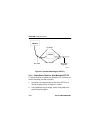
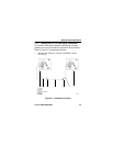
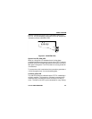
2. Using another AUI cable (6), connect the other LAN-MD (7)
to another FOT-F3 (5) attached to the same fiber optic link
segment as the FOT-F3.
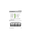
3. Select and run test 6 - SERVER on the LAN-MD connected
in step 1. Verify that this test passes.
• The status on the LAN-MD should read 000 if SQE is
enabled or 001 if SQE is disabled. A PASS TEST
STATUS LED should also be lit on the LAN-MD.
• This LAN-MD now acts as the SERVER unit and will act
as a packet echoer when used with another LAN-MD.
4. Select and run test 4 - NODE on the LAN-MD connected in
step 2. Verify that this test passes. At least 100 packets
should be sent and received with no errors. The packets
will be received and sent back from the SERVER LAN-MD
that was left running on the other segment.
When the FOT-F3 has successfully completed this test, the units
are ready for normal operation. If any failures are noted, please
contact Cabletron Systems Technical Support.
4.2 USING LANVIEW
The FOT-F3 Fiber Optic Transceiver uses Cabletron Systems
LANVIEW, a built-in visual diagnostic and status monitoring
system. LANVIEW LEDs are more effective than a network
monitor because a network troubleshooter can quickly scan the
LEDs to diagnose network problems and to determine which
node or segment is faulty.