


USING LANVIEW
FOT-F3 USER’S MANUAL 4-5
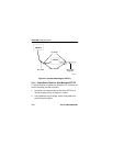
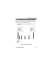
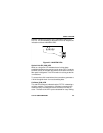
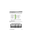
Figure 4-2 shows the location of the LANVIEW LEDs on the
FOT-F3. This is followed by a description of how to interpret the
indications of these LANVIEW LEDs.
Figure 4-2 LANVIEW LEDs
Optical Link OK (LNK) LED
When on, this green LED indicates that a link has been
established between the receive circuitry of the FOT-F3 and the
transmit circuitry of the fiber optic device at the other end of the
fiber optic link segment. This LED remains on as long as the link
is maintained.
To ensure that a link is maintained, the transceiver generates a
1 MHz idle signal when it is not transmitting data.
Collision (CLN) LED
This red LED flashes to indicate that the FOT-F3 is detecting a
collision condition. The frequency of flashes increases as the
network activity increases since more collisions are likely to
occur. The flash of the LED is pulse-stretched for easy viewing.
802.3 COMPATIBLE SINGLE MODE
FIBER OPTIC TRANSCEIVER
with LANVIEW
®
FOT-F3
SQE
P
W
R
S
Q
E
X
M
T
R
C
V
C
L
N
L
N
K
TX
RX
1300nm
0461-11