


Chapter 3: Installation
Page 3-22 NBR-SERIES Installation Guide
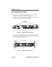
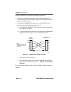
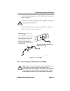
3. Attach the fiber labeled 2 to the applicable transmit port labeled TX,
on the module.
4. At the other end of the fiber optic cable, attach the fiber labeled 1 to
the transmit port of the device.
5. Attach the fiber labeled 2 to the receive port.
6. Check that the LNK LED on the applicable module port is on. If the
LED is not on, perform each of the following steps until it is:
a. Check that the device at the other end of the link is on.
b. Verify proper “crossover” of fiber strands between the applicable
port on the module and the fiber optic device at the other end of
the fiber optic link segment.
c. Verify that the fiber connection meets the dB loss specifications
outlined in Section C.1.2, Multimode Fiber Optic Network.
If you still cannot establish link, contact Cabletron Systems Technical
Support.
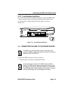
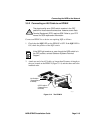
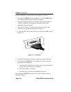
3.5.4 Connecting a Thin-Net Segment to an EPIM-C
Connect a thin-net segment to an EPIM-C as follows:
1. Set the Internal Termination Switch (see Figure 3-16), located to the
right of the port and labeled TERM, to either of the following
positions:
• The ON position ( ) to internally terminate the thin-net segment
at the port.
• The OFF position ( ) if you do not want the thin-net segment to
internally terminate at the port.
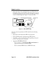
2. If the Internal Termination switch is in the ON position, connect the
thin-net segment directly to the BNC port.
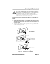
3. If the Internal Termination switch is in the OFF position, perform the
following steps:
a.
Attach a BNC tee-connector to the BNC port on the module.