


Modeling Manual Modeling Overview
Spectrum Enterprise Manager Page62 SmartSwitch 6000
For proper device management, the module’s
Device icons appear in a Topology view and you
may place the chassis’s Device icon in a Room
Location view. This is true whether you use
AutoDiscovery or manual modeling, In some
instances, this may require you to copy and paste
Device icons into the proper SPECTRUM views.
The manual modeling instructions given in this
section describe how this is accomplished.
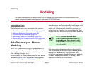
Manual Modeling Overview
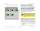
The following alternatives exist for modeling your
network components manually.
• Modeling using the chassis IP address in a
Location View. Create a chassis model within
a Room Location view using the chassis’s IP
address. Once the chassis is modeled,
SPECTRUM’s distributed management
feature identifies and models the modules
contained in the chassis and places their
Device icons in the chassis’s Container view.
You then copy and paste the Device icons into
the Topology view.
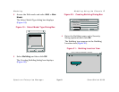
• Modeling using in the Topology view. You
can also create the chassis IP address in the
Topology view by modeling with the chassis’s
IP address in the Topology view and all the
models in the chassis will appear here. Locate
the chassis Device icon in the Find view.
Access the Find you by selecting View>New
View> Find. Select an attribute by which you
can search for your Chassis. Create a Room
Location view and copy the chassis Device
icon into the Room Location view.
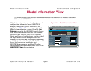
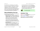
Container View
Access: From the Icon Subviews men for the Chassis
Device icon, select Container.
This view (Figure 18) displays Location view
Device icons for each module modeled in
SPECTRUM and contained in the chassis.
Note:
Note:
This only works when models are in
the distributed mode.