


INSTALLATION
Page 3-8
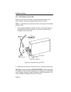
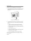
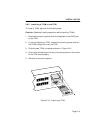
3.6 CONNECTING THE TRXI TO THE POWER SOURCE
Note: The TRXI has a universal power supply. This allows you to
connect the TRXI to power sources from 85 Vac to 264 Vac, 47-63 Hz.
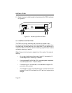
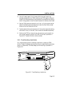
To connect the TRXI to the power source, plug the power cord into a
grounded wall outlet. Turn on the power switch at the back panel of
the TRXI. Verify that the PWR LED is lit, indicating that the TRXI is
receiving power. After the TRXI runs a self test, the CPU LED blinks
green indicating normal operation. If the LED remains red, the
processor is faulty.
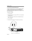
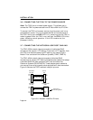
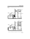
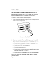
3.7 CONNECTING THE NETWORK LOBE PORT CABLING
The TRXI-22/24 network lobe ports consist of unshielded RJ45
connectors that support UTP cabling. To connect a UTP segment from
the TRXI to a station supporting STP cabling, you need a Type 3
Media Filter available from Cabletron Systems (TRMF, TRMF-2).
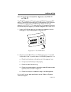
The TRXI-42/44 network lobe ports consist of shielded RJ45
connectors that support STP cabling. Shielded patch cables that adapt
a shielded RJ45 to a data connector (MIC) are available from
Cabletron Systems (PN 9372057-8). These adapter/patch cables let
you connect to an existing patch panel equipped with data connectors.
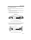
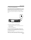
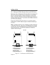
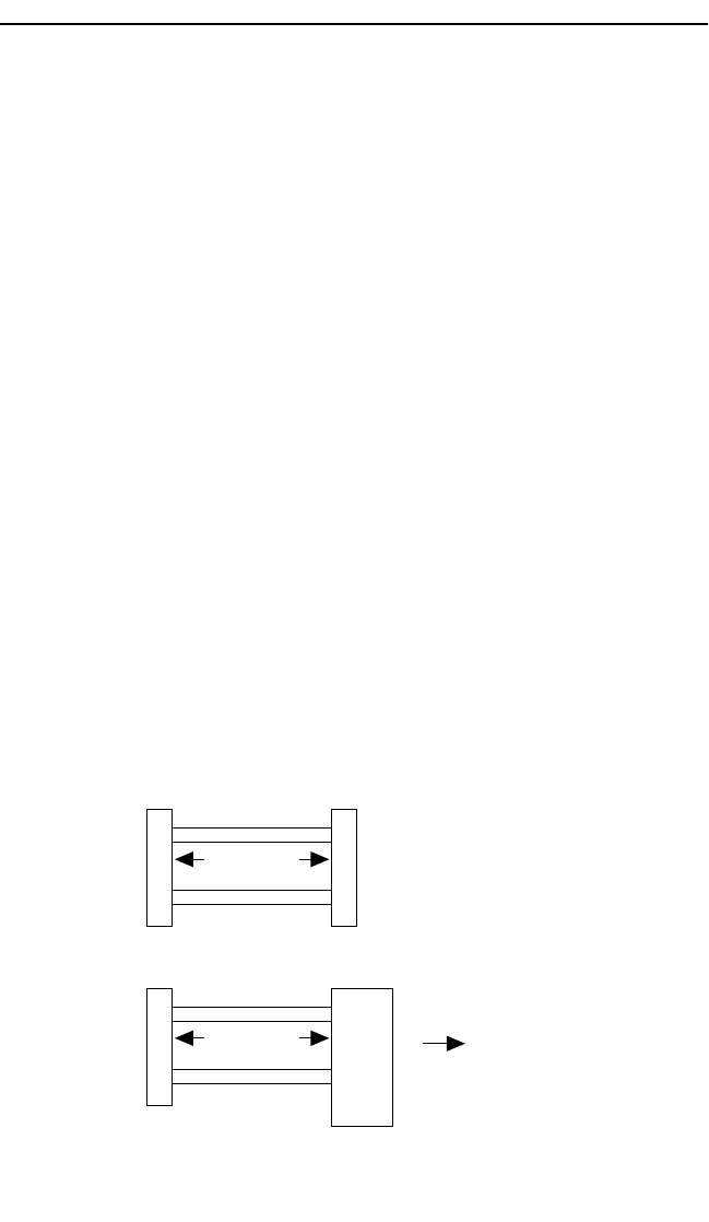
Figure 3-8 shows the TRXI’s network lobe port pinouts.
Figure 3-8. Network Lobe Port Pinouts
3
4
5
6
RX-
TX+
TX-
RX+
RJ45 to RJ45
TRXI-22/24
TCU Port
Device
Port
3
4
5
6
TX-
RX+
RX-
TX+
3
4
5
6
RX-
TX+
TX-
RX+
RJ45 to MIC
TRXI-42/44
TCU Port
Data Connector
(MIC)
Green
Orange
Black
Red
Shield
TX-
RX+
RX-
TX+
Patch Panel/
Token Ring Station