


TESTING AND TROUBLESHOOTING
Page 4-2
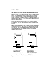
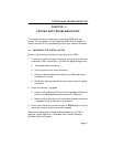
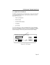
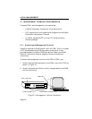
4.2 USING LANVIEW LEDs
LANVIEW is Cabletron Systems’ built-in visual diagnostic and status
monitoring system. Using LANVIEW, your network troubleshooting
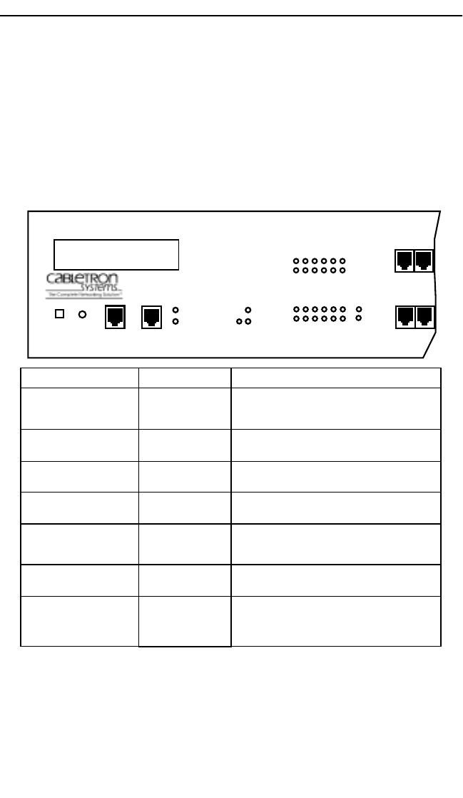
personnel can quickly scan the LANVIEW LEDs to observe network
status or diagnose network problems, and determine which node or
segment is faulty. Figure 4-1 describes each of the front panel
LANVIEW LEDs.
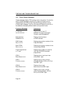
Figure 4-1. LANVIEW LEDs
LED NAME
Lobe Port Status
(Ports 1-24)
RI/RO
(Ring In/Ring Out)
PWR
(Power)
16 Mb/s
(Ring Speed)
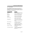
ACT
(Network Activity)
MGMT
(Network Management)
CPU
(Cental Processing Unit)
LED COLOR
Off
Green (Solid)
Green (Blinking)
Green (Solid)
Red (Solid)
Off
Green (Solid)
Yellow (Solid)
Off
Green (Flashing)
Red (Flashing)
Off
Green (Solid)
Red (Solid)
Off
Green (Flashing)
Green (Blinking)
Red (Solid)
DEFINITION
Port Enable-No Link or Port Disable-No Link
Port Enable-Link
Port Disable-Link or Ring Speed Fault
TPIM Inserted
TPIM Not Inserted
No Power
Power
16 Mbps Ring Speed
4 Mbps Ring Speed
Good Frames
Beacon Frames
No Activity
Management Agent Inserted
Management Agent Not Inserted
CPU In Boot Process
CPU Initializing
CPU Functioning
CPU Not Functioning
DISPLAY
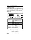
TRXI-24A TOKEN RING HUB WITH LANVIEW®
24 23
COM 2
COM 1
18 17 16 15 14 13
6 5 4 3 2 1
24 23 22 21 20 19
12 11 10 9 8 7
RO
RI
PWR
CPU
ACT
MGMT
16 Mb/s
RESET
DISPLAY
12 11
“Blinking” indicates a steady LED pulse.
Note: “Flashing” indicates an irregular LED pulse.