


Appendix B. CS I/O Connection
B.1 CS I/O 9-Pin Connection
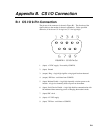
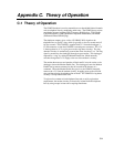
The pin out of the connector is shown in Figure B-1. The direction of the
signal relative to the modem is shown in parenthesis. Unless specified
otherwise, all levels are 0 V for logic low, 5 V for logic high.
FIGURE B-1. CS I/O Pin Out
1. (input) +5 VDC supply. Not used by COM220.
2. (input) Ground
3. (output) Ring - a logic high signifies a ring signal has been detected
4. (output) RX Data - serial data from COM220
5. (input) Modem Enable - a logic high internally switches power to the
modem. A logic low internally shuts off power to the modem.
6. (input) Serial Device Enable - a logic high disables communication with
the modem without removing power or changing the modem's mode.
7. (input) SDC clock. .
8. (input) +12 VDC supply
9. (input) TX Data - serial data to COM220
B-1