


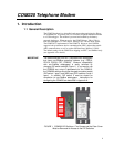


COM220 Telephone Modem
Table of Contents
PDF viewers note: These page numbers refer to the printed version of this document. Use
the Adobe Acrobat® bookmarks tab for links to specific sections.
1. Introduction..................................................................1
1.1 General Description..................................................................................1
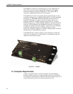
1.2 Computer Requirements ...........................................................................2
2. Specifications ..............................................................3
3. Installation....................................................................3
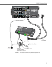
3.1 Connecting to Datalogger.........................................................................3
3.2 Connecting to Earth Ground.....................................................................4
3.3 Telephone to MD485 or Telephone to RF Systems..................................4
3.4 Telephone Service ....................................................................................4
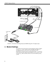
4. Modem Settings ........................................................... 6
5. Troubleshooting .......................................................... 7
Appendices
A. Changing COM220 Settings ................................... A-1
A.1 DIP Switch Settings............................................................................ A-1
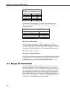
A.2 Hayes AT Commands......................................................................... A-2
A.3 Downloading a New Operating System to the COM220.................... A-6
A.4 Program Examples.............................................................................. A-7
A.4.1 ModemCallback Example (for CR1000) .................................. A-7
A.4.2 DialModem Example (for CR1000).......................................... A-8
A.4.3 P97 Instruction (for CR10X)..................................................... A-9
A.4.4 Example Programs for Data-Callbacks via a CR1000
Datalogger Router .............................................................. A-11
B. CS I/O Connection................................................... B-1
B.1 CS I/O 9 Pin Connection......................................................................B-1
C. Theory of Operation................................................ C-1
C.1 Theory of Operation.............................................................................C-1
i