


10
CONNECTING THE PROJECTOR
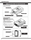
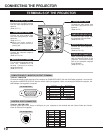
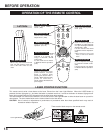
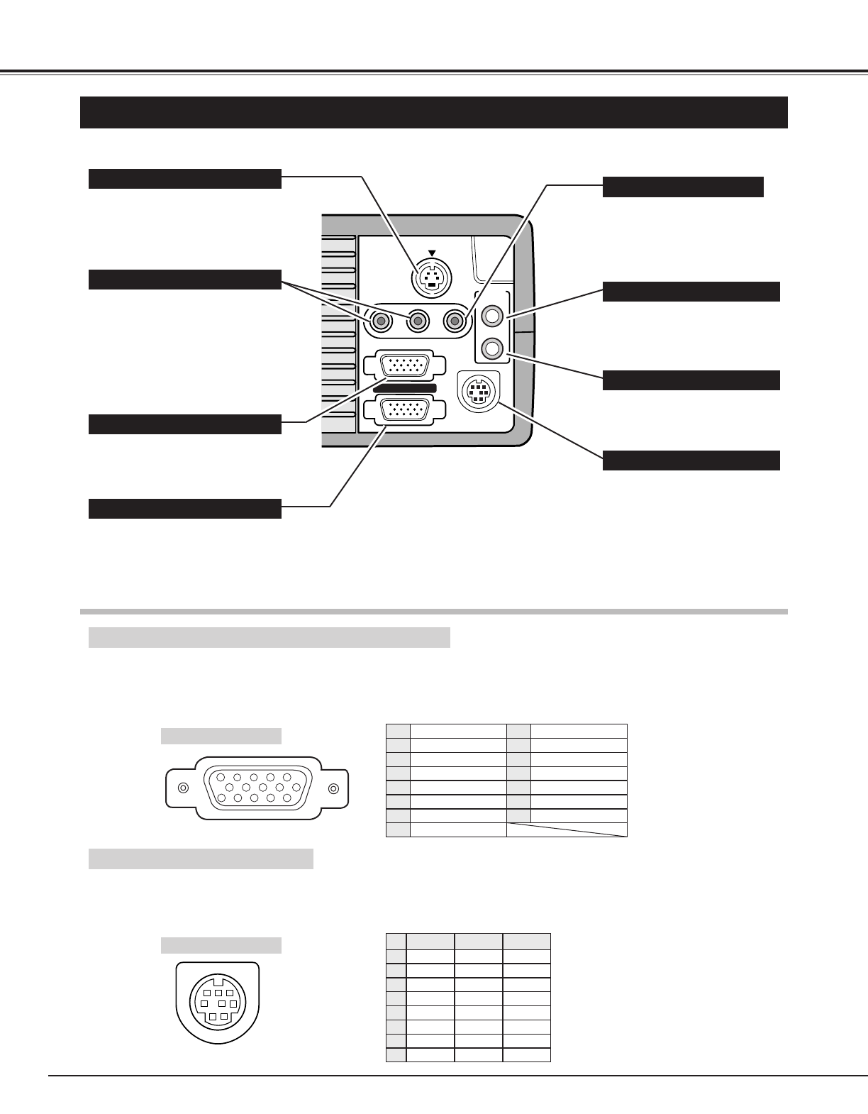
TERMINALS OF THE PROJECTOR
S-VIDEO
R-AUDIO-L
(MONO)
VIDEO
AUDIO
IN
OUT
CONTROL PORT
COMPUTER IN
MONITOR OUT
Connect the computer output to
this terminal.
(Refer to P12, 13.)
When controlling the computer
with the Remote Control of this
projector, connect the mouse
port of your personal computer
to this terminal.
(Refer to P12, 13.)
This terminal outputs the signal
from the COMPUTER IN
terminal. Connect to a monitor
using this terminal.
(Refer to P12, 13.)
Connect the audio amplifier to
this terminal.
(Refer to P12, 13.)
Connect the S-VIDEO output
from the video equipment to this
terminal.
(Refer to P11.)
Connect the audio output from
the computer to this terminal.
(Refer to P12, 13.)
Connect the audio outputs from
the video equipment to these
terminals.
(Refer to P11.)
● When the audio output is
monaural, connect it to the L
(mono) jack.
COMPUTER INPUT TERMINAL
MONITOR OUTPUT TERMINAL
CONTROL PORT CONNECTOR
COMPUTER AUDIO INPUT JACK
AUDIO INPUT JACKS
VIDEO INPUT JACK
S-VIDEO INPUT JACK
AUDIO OUTPUT JACK (STEREO)
Connect the video output from
the video equipment to this
terminal.
(Refer to P11.)
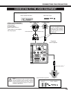
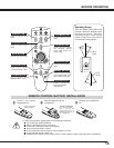
COMPUTER INPUT / MONITOR OUTPUT TERMINAL
Terminal : HDB15-PIN
Connect the display output terminal of the computer to COMPUTER INPUT with the VGA Cable (supplied). And connect
the monitor to MONITOR OUTPUT with the monitor cable (not supplied). When connecting the Macintosh computer, the
MAC Adapter (not supplied) is required.
5
1
2
34
10
9 678
15
14 13
11
12
Red Input
Ground (Horiz.sync.)
Green Input
Sense 2
Blue Input
Ground (Red)
Ground (Green)
Ground (Blue)
1
5
2
4
3
6
7
8
Non Connect
Horiz. sync.
Ground (Vert.sync.)
Sense 1
Sense 0
Vert. sync.
Reserved
9
13
10
12
11
14
15
Pin Configuration
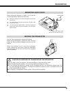
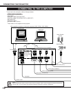
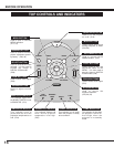
Terminal : Mini DIN 8-PIN
Connect control port (PS/2, Serial or ADB port) on your computer to this terminal with the Control Cable (the Control
Cable for PS/2 port is supplied).
1
2
3
4
5
8 7 6
Pin Configuration
CONTROL PORT CONNECTOR
-----
CLK
DATA
GND
-----
-----
GND
-----
R X D
-----
-----
GND
RTS
T X D
GND
GND
-----
ADB
-----
GND
-----
-----
-----
GND
PS/2 Serial ADB
1
2
3
4
5
6
7
8