


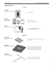
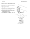
Instruction Manual SMART-LIFT 236 Electric Ceiling Lifts
13
ADJUSTMENTS
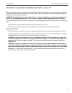
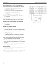
Adjust Travel
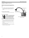
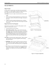
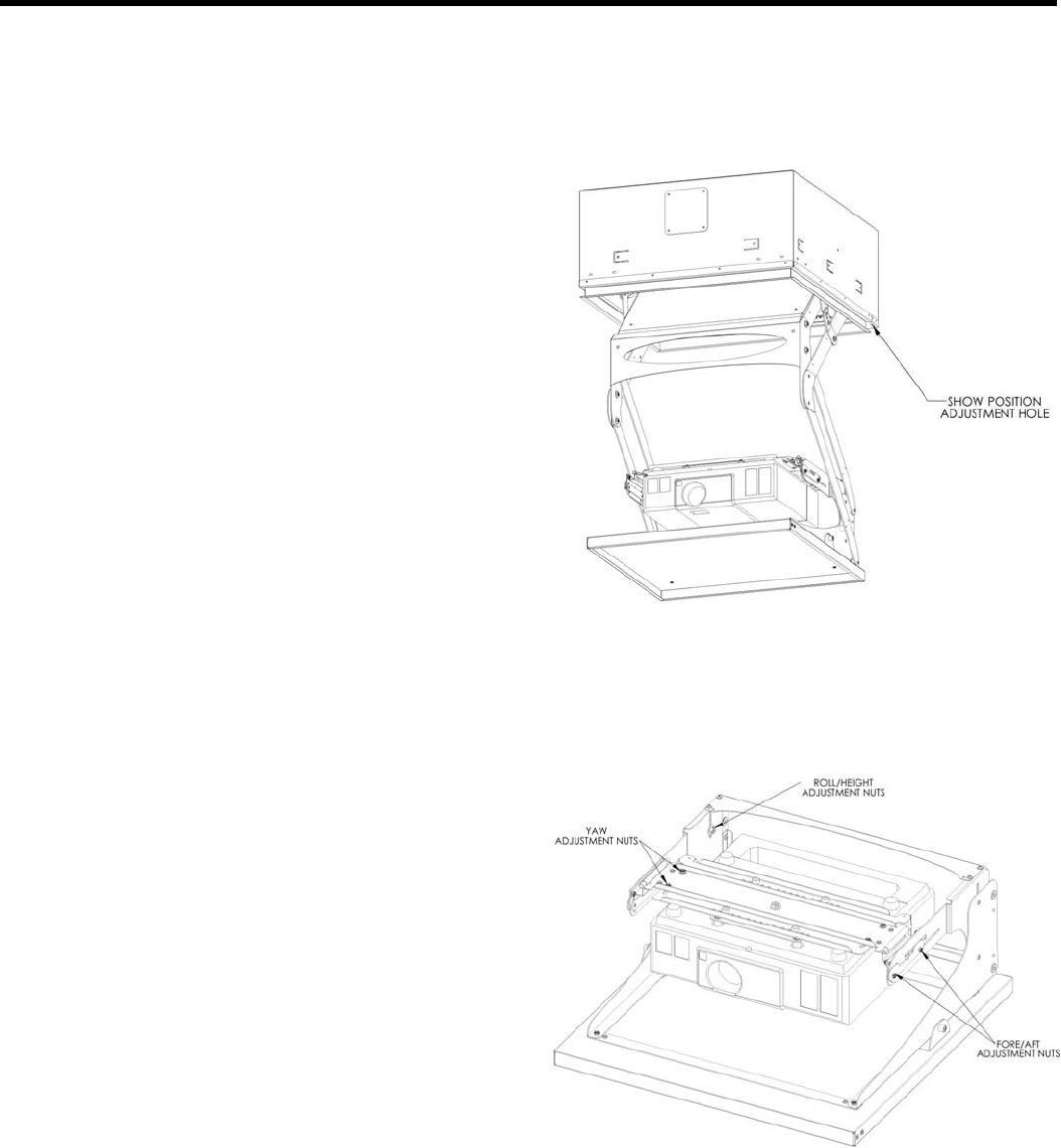
An access hole is located in the corner below the terminal block
(see Figure 11). Using a Phillips screwdriver inserted in the access
hole, adjust the stroke of the lift mechanism as follows:
CAUTION: Do not over adjust (exceed maximum travel) stroke
length.
1. Shorten stroke by turning the adjustment screw clockwise one
or two turns, check for the desired stroke length, and repeat as
necessary.
2. Lengthen stroke by turning the adjustment screw clockwise
one or two turns, check for the desired stroke length, and repeat
as necessary.
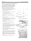
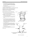
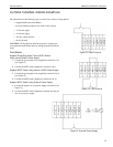
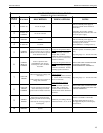
Adjust the Aim of the Projector
Center the lens (see Figure 12). The aim of the projector can be
adjusted in all directions, as shown:
1. Lower the lift to the 'show' position.
2. Pitch and forward/Aft. There are four 10-24 Nylock nuts
(two on each side) on the outside of the carriage. Loosen these
nuts slightly, tip the carriage in the slotted holes to the desired
angle, and tighten the nuts. For forward and aft adjustment,
loosen the four pitch adjustment nuts. Lift slightly, moving for-
ward or aft until tray falls into desired notch and tighten the
nuts.
CAUTION: Each side must be adjusted equally. Failure to adjust
each side equally may result in equipment and lift damage
when the lift closes.
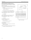
3. Roll/Height. There are four 1/4-20 nuts at the rear inside cor-
ners of the cradle assembly. Slightly loosen these nuts, gently
raise or lower the cradle to the desired position, and tighten the
nuts.
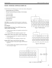
4. Ya w. There are four 10-24 Nylock nuts (two on each side) on
the top of the carriage. Loosen these screws slightly, turn the
carriage in the slotted holes to the desired angle, and tighten
the nuts.
Figure 11. Travel Adjustment
Figure 12. Projector Adjustment