


Installation Instructions XSM/XTM Series
7
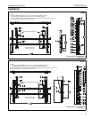
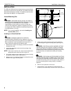
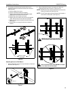
Figure 2
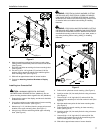
8. Mark the attachment points for the lower mounting slots,
making sure the attachment points are located on the studs.
(See Figure 2)
9. Drill 7/32" pilot holes at markings for lower mounting holes.
(See Figure 2)
10. Use two 5/16 x 2-1/2" lag bolts (LC) and two 5/16" flat
washers (LB) to attach the mount to the wall through the
lower mounting holes. (See Figure 2)
11. Slide rails to approximate center of screen location.
12. Proceed to Attaching Interface Brackets to Display
section.
Installing to a Concrete Wall
CAUTION: MINIMUM HORIZONTAL DISTANCE
BETWEEN WALL BRACKETS IS 24" (609.6mm). Do not
place mounting brackets closer together than 24" (609.6mm).
1. Determine the center of the display, and where it should be
located on the wall.
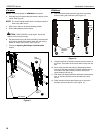
2. Line up the notches on mount with center of screen marking
to determine vertical center. (See Figure 1)
3. Measure up 7-1/2" (190.5mm) from the center point to mark
location of the upper mounting slots. (See Figure 1)
4. Using a level, mark the wall through both upper mounting
slots. (See Figure 3)
WARNING: ELECTRICAL SHOCK HAZARD! CUTTING
OR DRILLING INTO ELECTRICAL CORDS OR CABLES
CAN CAUSE DEATH OR SERIOUS PERSONAL INJURY!
ALWAYS make certain area behind mounting surface is free
of electrical wires and cables before drilling or installing
fasteners.
WARNING: EXPLOSION AND FIRE HAZARD! CUTTING
OR DRILLING INTO GAS PLUMBING CAN CAUSE DEATH
OR SERIOUS PERSONAL INJURY! ALWAYS make certain
area behind mounting surface is free of gas, water, waste, or
any other plumbing before cutting, drilling, or installing
fasteners.
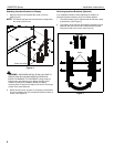
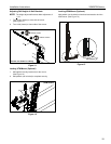
Figure 3
5. Drill one 5/16" pilot hole at each marking. (See Figure 3)
6. Install an anchor (LA) into each pilot hole using a hammer.
(See Figure 3)
7. Use two 5/16 x 2-1/2" lag bolts (LC) and two 5/16" flat
washers (LB) to attach top of mount to anchors in wall. (See
Figure 3)
8. Mark the attachment points for the lower mounting slots.
(See Figure 3)
9. Drill one pilot hole at each marking for lower mounting
holes. (See Figure 3)
10. Install an anchor (LA) into each pilot hole using a hammer.
(See Figure 3)
11. Use two 5/16 x 2-1/2" lag bolts (LC) and two 5/16" flat
washers (LB) to attach the mount to the wall through the
lower mounting holes. (See Figure 3)
12. Slide rails to approximate center of screen location.
8
9
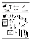
5
6
(LB) x 4
7
10
(LC) x 4
8
5
6
4
9
x4
(LA) x 4
10
7 11
(LC) x 4
(LB) x 4