


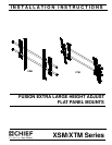
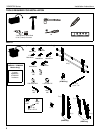

Installation Instructions XSM/XTM Series
9
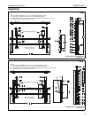
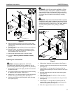
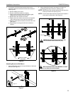
3. If necessary, the tilt interface bracket knobs may be
switched to allow the interface brackets to be reversed.
(See Figure 6)
a. Remove display from mount.
b. Remove interface brackets from display.
c. Hold the right interface bracket horizontally, tightly
gripping it so that spacers do not move.
d. Remove the knob, washer and screw.
e. Replace the knob, washer and screw in the opposite
order, with the knob on the inside of the bracket.
f. Switch the right interface bracket to the left side of the
wall mount.
g. Repeat Steps 3c through 3f with the left interface
bracket.
Figure 6
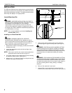
Attaching Screen to Wall Mount
1. Attach wall bracket caps (Q) to top and bottom of both wall
brackets. (See Figure 7)
Figure 7
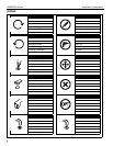
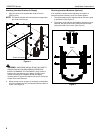
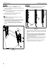
2. Adjust Velcro® pull strap (if necessary) so it does not
extend beyond bottom of screen. (See Figure 8)
NOTE: NEVER place both interface brackets to one side of the
wall mount center line! (See Figure 8)
NOTE: Do NOT allow both interface brackets to be located on
same side of wall bracket. (See Figure 8)
Figure 8
3d
3e
Knobs to outside
of brackets
(Q) x 4
1
Both interface brackets must NEVER be located
to one side of the wall brackets!
Pull strap
NEVER place both interface brackets to one
side of the wall mount center line (CL)!
Center Line (CL)