


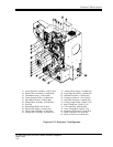


Projector Installation and Assembly
CHRISTIE DIGITAL SYSTEMS P35GPS Projector
March, 2004
3-3
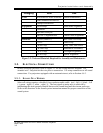
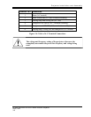
Category Item Use
Tools
Miscellaneous Allen wrenches General Maintenance
Small standard screwdriver
Phillips screwdrivers
Equipment
Oscilloscope Sound-head Alignment
Voltmeter
Real-time Analyzer
SK1994-3 alignment tool Lateral Guide Alignment
Materials
P35-BT (SMPTE) Buzz Track Test Loop
P35-FL Flutter Loop
Cat 69 Loop Dolby Tone, Pink Noise
Cat 566 Loop Illumination Uniformity
Cat 97 Loop Left/Right Alignment
RP-40 Loop Optical Alignment
Figure 3-2: Tools and Materials Required for Assembly and Maintenance
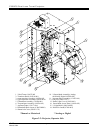
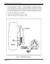
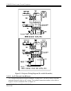
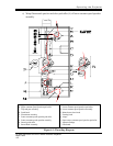
3.3. ELECTRICAL CONNECTIONS
Before wiring the projector, refer to Figure 3-3 for the wiring interface diagram. Use
stranded wire. Strip and tin the wire prior to connection. Use crimp connectors on all sound
connections. For projectors equipped with an automatic turret, refer to Section 6.6.3.
3.3.1. SOLAR C ELL WIRING
Solar cell wiring requires a shielded, four-conductor audio cable. (red – left (+), black – left
(-), green – right (+), white – right (-)). The best signal-to-noise ratio is achieved by
maintaining the same ground potential between the sound-head and the cinema processor.
Refer to the directions in the sound system instruction manual for proper connection of the
sound system.