


P35GPS Dual Lens Turret Projector
CHRISTIE DIGITAL SYSTEMS P35GPS Projector 4-2
March, 2004
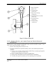
4.2.3. LENS INSTALLATION
3. Install lens system in lens holder. If it is necessary to open lens holder wider than
normal:
a) Loosen two lens-locking screws.
b) Turn jack screw clockwise until lens slides into lens holder.
3. Set focus knob at mid-position.
3. Secure lens system with two locking screws.
Over-tightening can cause focus mechanism to bind.
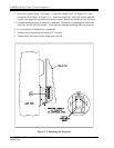
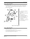
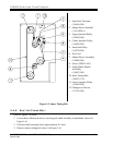
4.3. FILM THREADING AND OPERATING PROCEDURE
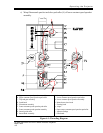
Refer to Figure 4-1 for film threading and positioning.
1. Set Ultramittent to its rest position. There should be no sprocket movement when manual
turndown knob (N) is turned.
2. Center framing knob (P) by aligning mark on knob with line on projector housing marked
CENTER FRAME.
3. Swing out pad rollers (B, F, and L) on upper constant-speed sprocket assembly (A),
center constant-speed sprocket assembly (G), and lower constant-speed sprocket
assembly (M).
4. Swing out film shoe on Ultramittent assembly (E).
5. Pull out catch knob (D) and swing out trap and gate assembly (C).
6. Using slightly more film length than is required to reach film transport system, begin to
thread film into projector.
7. Align film on Ultramittent sprocket and close Ultramittent film shoe.
8. To form proper loop between Ultramittent and center constant-speed sprocket assembly:
a) Pull film loosely over pad roller while pad roller is in open position (R) and then onto
center constant-speed sprocket.
b) Mate film sprocket holes with sprocket roller pins.
c) Hold film in position and close pad roller.
The required film loop has now been formed.
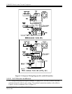
9. Thread film on sound-head assembly as shown in Figure 4-1:
a) Holding two lateral guide rollers (H and K) towards each other, pull film tight and
align film on lower constant-speed sprocket assembly (M).
b) Tighten film on one sprocket hole so lateral guides barely float off sound drum.