


Calibration, Alignment, and Adjustment Procedures
CHRISTIE DIGITAL SYSTEMS P35GPS Projector
March, 2004
6-7
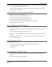
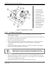
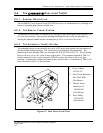
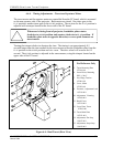
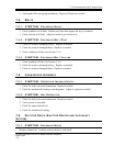
6.6. THE CHRISTIE DUAL-LENS TURRET
6.6.1. GENERAL D ESCRIPTION
The CHRISTIE Turret System for the P35GPS Projector is a mechanical device holding two
lenses in a rotating plate about a central axis.
6.6.2. THE M ANUAL T URRET SYSTEM
The position of each lens is set manually by turning the lens holder plate in the desired FLAT
or SCOPE lens position. The aperture opening matching the lens is also set manually by
moving the aperture handle on the trap and gate up for FLAT or down for SCOPE.
6.6.3. THE A UTOMATIC TURRET SYSTEM
The automatic turret is electronically driven by a DC motor that controls the movements of
the lens holder and the aperture. The electronics are initiated by the automation. The
interfacing is done through TB4 (see schematic for P/N 503226 or 503333). The switching
from SCOPE to FLAT or vice versa is done with a pulse. The common terminal of TB4-3 is
briefly connected to the SCOPE terminal of TB4-4 to move the turret to the SCOPE lens
position. A momentary connection between the COMMON and FLAT terminals of TB4-5 will
move the turret to the FLAT lens position.
1: Drive O-Ring
518734-191
2: Auto Turret Hardware
Kit. 196594-001
(Not Shown)
3: Manual Turret
Hardware kit
196594-002
(Not Shown)
4: Drive Pulley
197018-001
(Not Shown)
Figure 6-3: Dual Turret (Front View)