


11
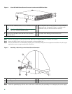
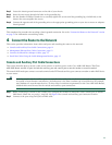
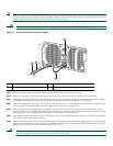
Step 5 Locate the chassis ground connector on the side of your chassis.
Step 6 Insert the two screws through the holes in the grounding lug.
Step 7 Use the Number 2 Phillips screwdriver to carefully tighten the screws until the grounding lug is held firmly to the
chassis. Do not overtighten the screws.
Step 8 Connect the opposite end of the grounding wire to the appropriate grounding point at your site to ensure an adequate
chassis ground.
This completes the procedure for attaching a chassis ground connection. Go to the “Connect the Router to the Network” section
on page 11 for information on attaching cables.
4 Connect the Router to the Network
This section provides information about cables and ports and attaching the router to the network.
• Console and Auxiliary Port Cable Connections, page 11
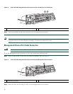
• Management Ethernet Port Cable Connection, page 12
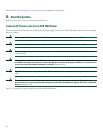
• Connect the Shared Port Adapter Cables, page 13
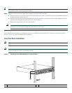
• Install the Cables Using the Cable-Management Bracket, page 13
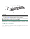
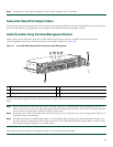
Console and Auxiliary Port Cable Connections
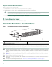
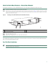
This section describes how to attach a cable to the console or auxiliary ports on the Cisco ASR 1002 Router. The Cisco
ASR 1002 Router uses RJ-45 ports for both the auxiliary port and console port to attach a modem or console terminal.
The console DCE-mode port connects a console terminal and a DTE-mode auxiliary port connects a modem or other DCE device
to your router.
Caution Both the console and the auxiliary ports are asynchronous serial ports; any devices connected to these ports must
be capable of asynchronous transmission. (Asynchronous is the most common type of serial device; for example,
most modems are asynchronous devices.) To meet Class A emissions requirements on the Cisco ASR 1002 Router,
shielded cables must be used for the console and auxiliary port connections.
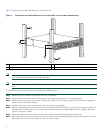
Step 1 Before connecting a terminal to the console port, configure the terminal to match the router console port as follows:
9600 baud, 8 data bits, no parity, 1 stop bits. See Figure 8 for console and auxiliary port connector location.
Step 2 Connect to the port using the RJ-45-to-DB-9 cable.