


17
Note The color coding of the DC-input power supply leads depends on the color coding of the DC power source at your site.
Typically, green or green/yellow is used for ground. Make certain the lead color coding you choose for the DC-input
power supply matches lead color coding used at the DC power source.
Warning
When you install the unit, the ground connection must always be made first and disconnected last.
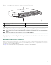
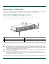
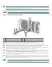
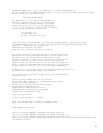
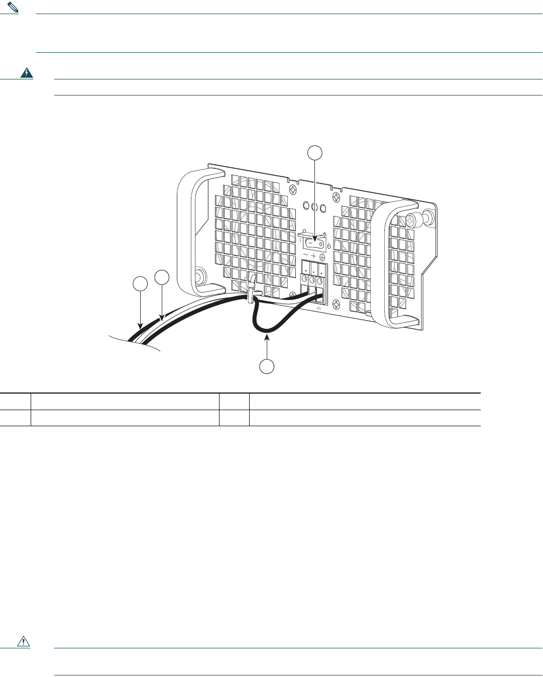
Figure 13 Cisco ASR 1002 Router DC Power Supply
Step 2 Ensure that the negative and positive leads are disconnected from the site power source.
Step 3 Using a wire stripper, strip approximately 0.55 inch (14 mm) from the positive, negative, and ground lead.
Step 4 Insert the stripped end of the ground lead all the way into the ground lead receptacle on the DC-input power supply,
and tighten the receptacle screw using a 3.5mm flat-blade screwdriver
to a torque of 0.5 to 0.6Nm.
Step 5 Insert the stripped end of the positive lead all the way into the positive lead receptacle and tighten the receptacle screw
using the same 3.5mm flat-blade screwdriver. Repeat this step for the negative lead.
Step 6 Make sure the entire stripped end of each lead is inserted all the way into its receptacle. If any exposed wire at the
stripped end of a lead is visible after inserting the lead into its receptacle, remove the lead from the receptacle, use the
wire stripper to cut the stripped end of the lead, and repeat Step 3 through Step 5.
Step 7 After tightening the receptacle screw for the ground, positive, and negative DC-input leads, use a cable tie to secure the
three leads to the power supply faceplate.
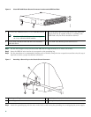
Step 8 When securing the earth ground, positive, and negative DC-input leads to the power supply faceplate, leave a service
loop in the ground lead to ensure that the ground lead is the last lead to disconnect from the power supply if a great
deal of strain is placed on all three leads as shown in Figure 13.
Caution Leave a service loop in the earth ground lead to ensure that the earth ground lead is the last lead to disconnect from
the power supply if a great deal of strain is placed on all three leads
1
Earth ground lead service loop area
3
DC power positive lead
2
DC power negative lead
4
Power supply standby switch
OUTPUT INPUT
FAIL
OK OK
FAN
-48V/-6
0V
16A
Th
i
s un
it m
ig
h
t
h
av
e
more
th
a
n
one power supply connection.
A
ll
con
n
e
ctions m
u
st
be rem
o
v
ed
to
d
e-
e
nergi
ze the unit.
3
1
2
280290
4