


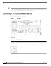


4
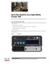
Quick Start Guide for Cisco Digital Media Encoder 1100
OL-17934-01
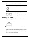
Connecting to an IP Network
Connecting to an IP Network
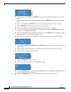
The encoder provides two network 1 Gigabit Ethernet network connections (Figure 3). These connectors
are also referred to as output connectors because the encoder sends video and audio over an IP network,
which these connections provide.
Figure 3 RJ-45 Ethernet Connector
Note If you are not familiar with network protocols, please contact your network administrator for assistance.
The encoder network settings default to dynamically obtain an IP address from a DHCP server on the
network.
If a DHCP server is not available or cannot be found on the network, then the encoder will assign its own
IP address.
For most network environments, it will not be necessary to modify these default settings. However, if
you wish to assign a static IP address to the encoder’s Network Interface Cards (NICs), then you can
change the network setting by using the encoder front panel menu. For detailed instructions, please refer
to the User Guide for Cisco Digital Media Encoder 1100.
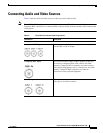
Analog Inputs—Audio
Unbalanced Audio Input These RCA connectors provide left and right stereo input.
RCA connectors are a standard consumer stereo audio
connection found on most video players and video cameras.
Balanced Audio Input These XLR connectors provide left and right balanced stereo
input. XLR connectors are used by professional audio
engineers and are found on high-end audio and video
playback equipment.
Note A microphone preamplifier or mixer with XLR
preamp functions is required to connect a XLR
microphone to the Balanced Audio Input.
Table 2 Rear Panel Connectors and Components (continued)