


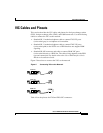


VIC Cables and Pinouts
vi
Cisco 1750 Router Hardware Installation Guide
78-6169-02
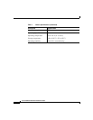
Note Pins that are not used should not be connected.
The E&M VIC pinout depends on the PBX type and connection. Table 5 lists the
pinout for this connector.
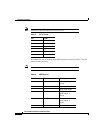
Note Pins that are not used should not be connected.
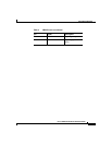
Table 4 RJ-11 Pinout
Pin Signal
1–
2–
3Ring
4Tip
5–
6–
Table 5 E&M Pinouts
Pin Signal Description
1 SB –48V signaling
battery
2 M-lead Signaling input
3 R Ring, audio input
4 R or R1 Ring, audio
input/output, or
output
5 T or T1 Tip, audio
input/output, or
output
6 T Tip, audio input