


3-2
Cisco 1805 DOCSIS Cable Router Hardware Installation Guide
OL-14661-01
Chapter 3 Chassis Installation Procedures for the Cisco 1805 DOCSIS Cable Router
Setting Up the Chassis
Caution The front panel bezel must not be removed from the Cisco 1805 cable router. It is part of the product’s
enclosure, and must be left in place to prevent damage from foreign parts entering the router, to provide
a shield from internal electromagnetic interference (EMI), and to direct the flow of cooling air properly
through the chassis.
Setting the Chassis on a Desktop
You can place Cisco 1805 cable routers on a desktop or shelf. The Cisco 1805 cable router is shipped
with the rubber feet attached to the chassis to provide space for air circulation.
Warning
To prevent personal injury or damage to the chassis, never attempt to lift or tilt the chassis using the
handles on modules (such as power supplies, fans, or cards); these types of handles are not designed
to support the weight of the unit.
Statement 1032
Caution Do not place anything on top of the router that weighs more than 10 pounds (4.5 kilograms). Excessive
weight on top of the router could damage the chassis.
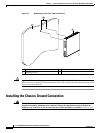
Chassis Grounding
After the router has been installed, you must connect the chassis to a reliable earth ground. For the
chassis ground connection procedure, see the “Installing the Chassis Ground Connection” section on
page 3-4.
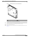
Wall-Mounting the Chassis
Warning
This unit is intended to be mounted on a wall. Please read the wall mounting instructions carefully
before beginning installation. Failure to use the correct hardware or to follow the correct procedures
could result in a hazardous situation to people and damage to the system.
Statement 248
The Cisco 1805 cable router can be wall-mounted by using two number 6, 3/4-inch screws and the
mounting features on the bottom of the router. (See Figure 3-1.) You must provide the screws. We
recommend using pan-head or round-head screws.