


3-5
Cisco 1805 DOCSIS Cable Router Hardware Installation Guide
OL-14661-01
Chapter 3 Chassis Installation Procedures for the Cisco 1805 DOCSIS Cable Router
Installing the Chassis Ground Connection
You must connect the chassis to a reliable earth ground, using a ground lug and size 14 AWG (2 mm
2
)
wire. To install the ground connection for a Cisco 1805 DOCSIS cable router, follow these steps:
Step 1 Strip one end of the ground wire to expose approximately 3/4 in. (20 mm) of conductor.
Step 2 Crimp the green14 AWG ground wire to a UL-Listed/CSA-certified ring terminal that is suitably sized
for the number 6 ground screw provided on the rear panel of the router. The crimping tool should be one
that is recommended by the ring lug terminal manufacturer.
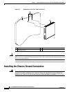
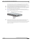
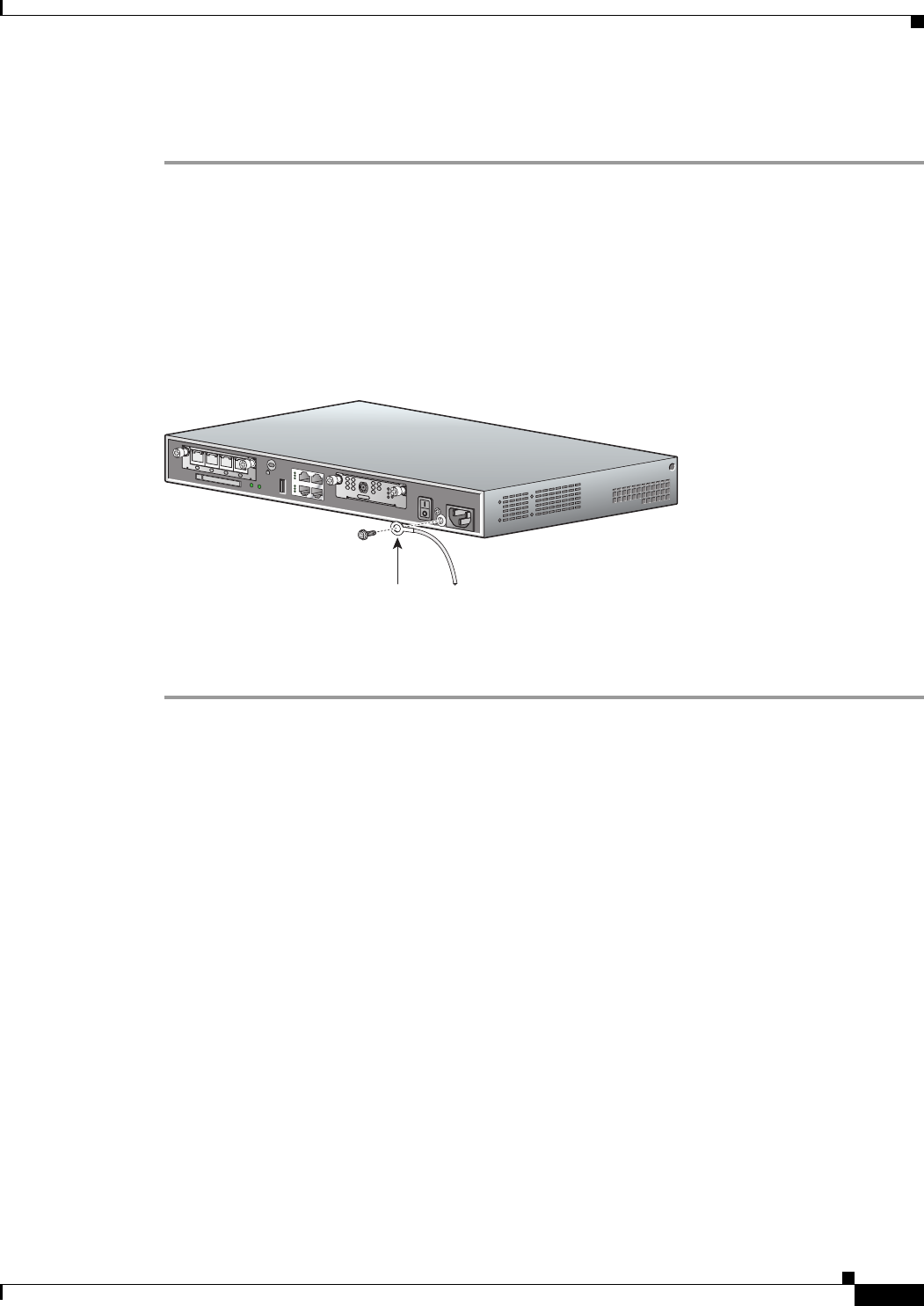
Step 3 Attach the ring terminal to the chassis. The attachment points for the cable router are shown in
Figure 3-3. Use a number 2 Phillips screwdriver and the screw supplied with the ground lug. Tighten the
screw to a torque of 8 to 10 in-lb (0.9 to 1.1 N-m).
Figure 3-3 Chassis Ground Connection on the Cisco 1805 Router
Step 4 Connect the other end of the ground wire to a known good electrical ground point. Please consult a
licensed electrician if you have any questions about the suitability of the ground connection.
After the router is installed and properly grounded, you can connect the WAN and LAN cables as
required for your installation.
232506
Ring terminal
attachment
CISCO 1841
100-240 VAC-
1 A
50/60 Hz
HWIC
4ESW
PWR3xLNKPWR2xLNKPWR1xLNKPWR0xLNK
LINK
US
ONLINE
HWIC-
CABLE-D-2
POWER
DS
CABLE