


18
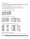
Step 2 Crimp the ground wire to the ground lug or ring terminal, using a crimp tool of the appropriate size.
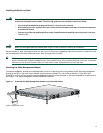
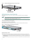
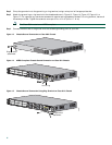
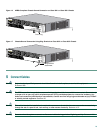
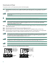
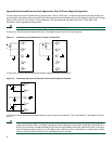
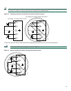
Step 3 Attach the ground lug or ring terminal to the chassis as shown in Figure 13, Figure 14, Figure 15, Figure 16, or
Figure 17. For a ground lug, use the two screws with captive locking washers provided. For a ring terminal, use one of
the screws provided. Tighten the screws to a torque of 8 to 10 in-lb (0.9 to 1.1 N-m).
Note The Cisco 2801 router is not NEBS-compliant.
Step 4 Connect the other end of the ground wire to a suitable grounding point at your site.
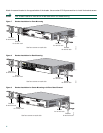
Figure 13 Chassis Ground Connection on Cisco 2801 Chassis
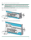
Figure 14 NEBS-Compliant Chassis Ground Connection on Cisco 2811 Chassis
Figure 15 Chassis Ground Connection Using Ring Terminal on Cisco 2811 Chassis
117082
Ring terminal
attachment
98808
Ground lug
A= ACT
FE 0/1
PVDM1 PVDM0 AIM1 AIM0
FE 0/0
S= SPEED
A= FDX
A= LINK
A
F
S
L
A
F
S
L
S
L
O
T
2
S
L
O
T
0
S
L
O
T
3
S
L
O
T
1
ENM0
103066
A= ACT
FE 0/1
PVDM1 PVDM0 AIM1 AIM0
FE 0/0
S= SPEED
A= FDX
A= LINK
A
F
S
L
A
F
S
L
S
L
O
T
2
S
L
O
T
0
S
L
O
T
3
S
L
O
T
1
ENM0
Ring terminal
attachment