


28
System Management Connections
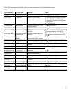
The connections described in Table 4 provide system management access.
6 Power Up the Router
Caution To ensure adequate cooling, never operate the router unless the cover and all modules and cover plates are installed.
Checklist for Power-Up
You are ready to power up the Cisco 2800 series integrated services router after the following steps are completed:
• Chassis is securely mounted and grounded. (See the “Install Chassis” section on page 6.)
• Power and interface cables are connected. (See the “Connect Cables” section on page 19.)
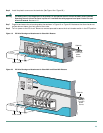
• Make sure that the external CompactFlash memory card is properly seated into the slot. For installation instructions, see
the online Cisco 2800 series hardware installation documentation at the following URL:
http://www.cisco.com/univercd/cc/td/doc/product/access/acs_mod/2800/hw/index.htm
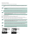
• PC with terminal emulation program is connected to the console port, powered up, and configured for 9600 baud, 8 data
bits, 1 stop bit, no flow control, and no parity. (See the “System Management Connections” section on page 28.)
• Suitable PC COM port is selected in the terminal emulation program.
Note For initial power-up, a direct console connection is recommended. After the initial configuration is completed, a remote
modem connection can be used for router management.
Caution To ensure adequate cooling, never operate the router unless the cover and all modules and cover plates are installed.
Caution To prevent damage to the ejector mechanism, the ejector button next to the CompactFlash card must remain fully
seated when not being used to eject a CompactFlash card.
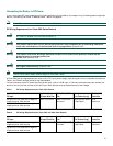
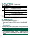
Table 4 System Management Connections
Port Color Connection Cable
Console Light blue PC or ASCII terminal communication port
(usually labeled COM)
RJ-45-to-DB-9 console cable
Auxiliary Black Modem for remote access RJ-45-to-DB-25 modem cable
Universal serial bus (USB) — Peripheral devices USB cable