2-7
Catalyst 2900 Series XL Hardware Installation Guide
78-6461-03
Chapter 2 Installation
Installing the Switch on a Table or Shelf
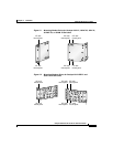
• Mounting kit containing these items:
–
Four rubber feet for mounting the switch on a table, shelf, or desk
–
Two mounting brackets
–
Four number-12 Phillips machine screws for attaching the brackets to a
rack
–
Four number-8 Phillips flat-head screws for attaching the brackets to the
switch (19-inch rack mount)
–
Four number-8 Phillips truss-head screws for attaching the brackets to
the switch (24-inch rack mount)
–
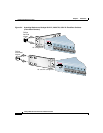
One cable guide and one (two for modular switches) black Phillips
machine screw for attaching the cable guide to one of the mounting
brackets
Note The cable guide is not applicable for the Catalyst 2912 LRE XL
and 2924 LRE XL switches.
• One RJ-45-to-RJ-45 rollover cable
• One RJ-45-to-DB-9 adapter
• Cisco Information Packet, containing warranty, safety, and support
information
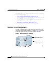
Installing the Switch on a Table or Shelf
Follow these steps to install the switch on a table or shelf:
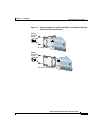
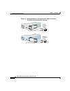
Step 1 Locate the adhesive strip with the rubber feet in the mounting-kit envelope.
Attach the four rubber feet to the recessed areas on the bottom of the unit.
Step 2 Place the switch on the table or shelf near an AC power source.
Step 3 After the switch is mounted on the table or shelf, power the switch as described
in “Powering On the Switch and Running POST” sectiononpage2-25.


