


2-5
Cisco Catalyst Blade Switch 3030 Hardware Installation Guide
OL-8389-01
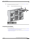
Chapter 2 Switch Installation
Dell Modular Server Chassis Architecture
Dell Modular Server Chassis Architecture
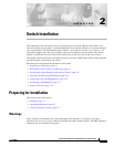
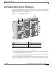
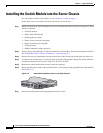
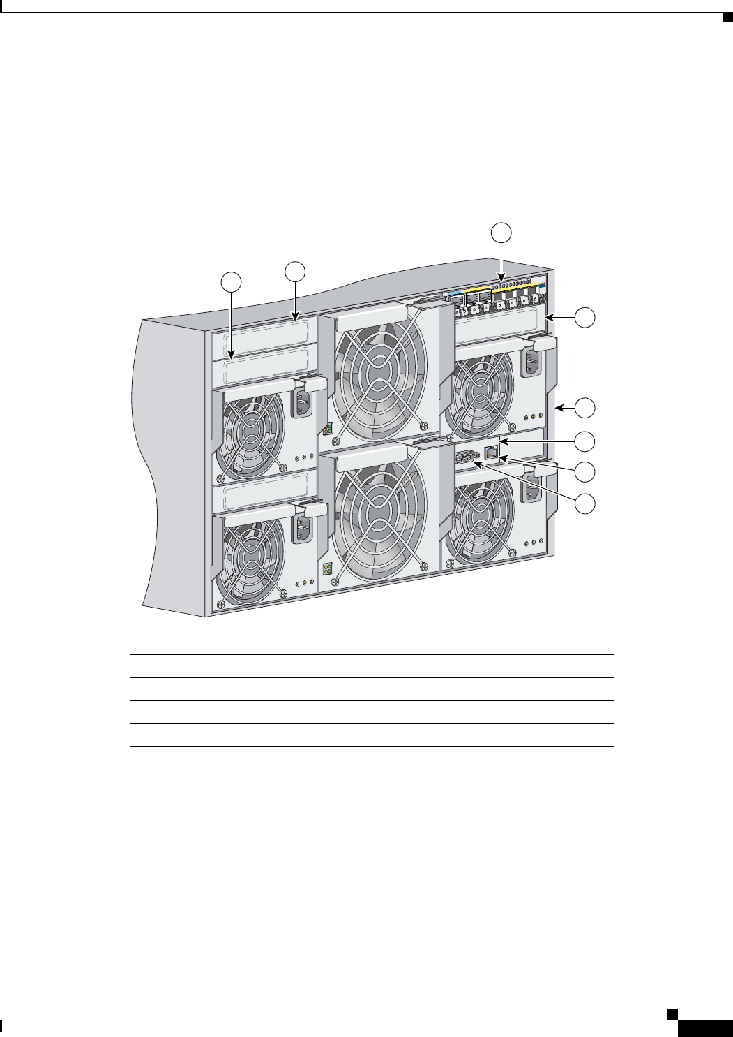
The four chassis I/O module bays are on the rear panel (see Figure 2-1). You can insert switch modules
into the chassis I/O module bays 1 and 2. Use bays 3 and 4 for switch modules only if a Gigabit Ethernet
daughter card is installed on the server modules.
Figure 2-1 Dell Modular Server Chassis
Consider these prerequisites before installing your switch module:
• Bay 1 and bay 2 are a pair. Bay 1 must be populated before bay 2. If bay 2 is used, the I/O module
in bay 2 must be the same type as the one in bay 1.
• Bay 3 and bay 4 are a pair. Bay 3 must be populated before bay 4. If bay 4 is used, the I/O module
in bay 4 must be the same type as the one in bay 3.
For more information about the components of the information panel, see the Dell PowerEdge 1855
Systems User's Guide and the Dell PowerEdge 1855 Systems Installation and Troubleshooting Guide.
1 Bay 1 (populated with switch module) 5 Rear panel of server chassis
2 Bay 2 6 DRAC/MC
1
management board
1. DRAC/MC: Dell Remote Access Controller/Modular Chassis management board
3 Bay 3 7 Ethernet port
4 Bay 4 8 RS-232 port
143471
11x
12x
13x
14x
15x
16x
C
o
n
s
o
le
11x
12x
13x
14x
15x
16x
2
1
3
5
6
4
7
8