


1-14
Catalyst 3650 Switch Hardware Installation Guide
OL-29734-01
Chapter 1 Product Overview
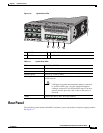
Front Panel
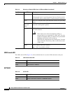
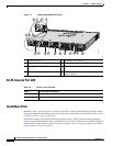
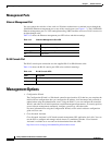
Uplink Ports LEDs
The four uplink ports have four status LEDs. Each port LED is labeled according to its SFP and SFP+
module status.
For SFP ports, a G(x) labeling nomenclature is used, where G = 1 Gigabit and x = the port number. The
The G(x) label appears to the left of the uplink port LED.
For SFP+ ports, a TE(x) labeling nomenclature is used, where TE = 10 Gigabit and x = the port number.
The TE(x) label appears to the right of the uplink port LED.
An SFP+ module ports has two labels, G(x) and TE(x), because it supports both SFP and SFP+ modules.
The uplink port labeling layouts for the various switch models are:
• Four uplink port LEDs labeled G1, G2, G3, G4—This labeling represents four ports supporting SFP
modules.
• Four uplink port LEDs labeled G1, G2, G3, G4 and two right side uplink ports LEDs also labeled
TE3 and TE4—This labeling represents two ports (left side) supporting SFP modules and two ports
(right side) supporting SFP and SFP+ modules.
• Four uplink port LEDs labeled G1, G2, G3, G4 and TE1, TE2, TE3, TE4—This labeling represents
four slots supporting SFP and SFP+ modules.
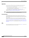
Figure 1-6 shows an example of an uplink ports LED arrangement representing two SFP and two SFP+
ports (Catalyst 3650-48FD-S switch model).
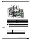
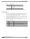
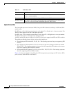
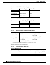
Table 1-7 PoE+ Mode LED
Color PoE+ Status
Off PoE mode is not selected. None of the 10/100/1000 ports have been denied power
or are in a fault condition.
Green PoE mode is selected, and the port LEDs show the PoE+ status.
Blinking amber PoE mode is not selected. At least one of the 10/100/1000 ports has been denied
power, or at least one of the 10/100/1000 ports has a PoE+ fault.