


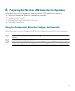

16
Step 16
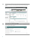
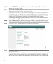
From the LWAPP Transport Mode drop-down box, choose Layer 3. The controller
operates only in Layer 3 mode.
Step 17
(Optional) In the RF Mobility Domain Name field, enter the name of the mobility group/
RF group to which you want the controller to belong.
Although the name that you enter here is assigned to both the mobility group and the RF
group, these groups are not identical. Both groups define clusters of controllers, but they
have different purposes. All of the controllers in an RF group are usually also in the same
mobility group and the reverse. However, a mobility group facilitates scalable,
system-wide mobility and controller redundancy, while an RF group facilitates scalable,
system-wide dynamic RF management.
Step 18
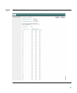
In the Country Code field, enter the code for the country in which the controller will be
used. See the table below the Country Code field for the list of available country codes.
Step 19
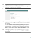
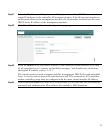
Click Next. The AP Manager Interface Configuration page appears.
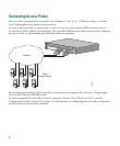
Step 20
Enter the VLAN identifier, the IP address, the netmask, and the gateway for the controller
AP-manager interface.
The AP-manager interface is used for Layer 3 communications between the controller and
lightweight access points and must have a unique IP address. It is usually configured on
the same VLAN or IP subnet as the management interface, but this is not a requirement.