


14 Part Number 4021203 Rev A
Back Panel Description
Back Panel Description
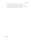
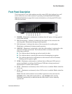
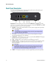
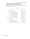
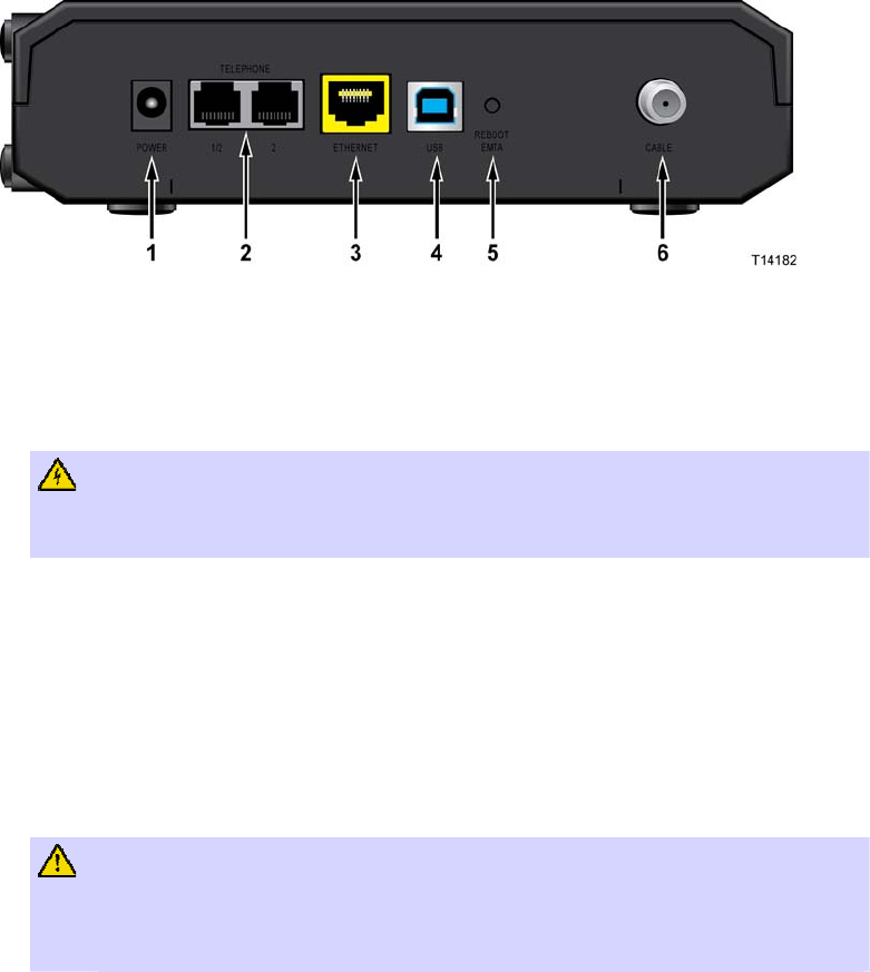
The following illustration shows the description and function of the back panel
components on the DPC3212 and EPC3212.
Do not connect your PC to both the Important: ETHERNET and USB ports at the
same time. Your modem will not function properly if both the
ETHERNET and USB
ports are connected to your PC at the same time.
POWER – Connects the cable modem to the AC power supply that is provided
with your cable modem
1
CAUTION:
Avoid damage to your equipment. Only use the AC power adapter that is
provided with your cable modem.
2 TEL 1/TEL 2 – RJ-11 telephone ports connect to home telephone wiring to
conventional telephones or fax machines
3
ETHERNET – RJ-45 Ethernet port connects to the 10/100/1000BASE-T Ethernet
port on your PC or your home network
– 12 Mbps USB 1.1 port connects to the USB port on your PC USB
4
REBOOT EMTA – Pressing this switch reboots the EMTA. Pressing this switch
for more than three seconds resets the device to factory default values and
reboots the EMTA
5
CAUTION:
The REBOOT EMTA button is for maintenance purposes only. Do not use
unless instructed to do so by your service provider. Doing so may cause
you to lose any cable modem settings you have selected.
– F-Connector connects to an active signal from your service provider 6 CABLE